Friday, March 31, 2017

Scratch Building a Gas Mechanical Critter Part 2

In the first installment of this series, I discussed how I built the brass underframe for my "critter" to serve as a base for the engine frame and the decking.  The cab, motor housing and other details will be constructed from styrene and will rest on the deck.

With the brass underframe complete, my next task was to build up the side frames and end beams from styrene sheet, channel, angle and other styrene strips.   The parts were cut to fit around the underframe and test fit before gluing the assembly together with Plastruct cement.


Clearly the frame needed more detail to resemble the prototype model I found on the internet.  A quick glance at the photo I was using for inspiration reveals some interesting journal boxes, an access door of some kind, coupler pockets and ladders.


For journal boxes, I chose Grandt Line C&S caboose boxes and lids.  They were as close as I could come to the ones in the photo.  After allowing for the height and location of the Stanton Drive wheels, I cemented the journal boxes in place.  Almost immediately, the frame began to look more interesting.


For the end beam, I cut holes for the couplers in the styrene, and used tin snips to cut out the brass underframe where the couplers would go. The coupler pockets and the front and rear pilot steps were constructed from Evergreen angle stock in various sizes.  I used Evergreen V Groove .100" sheet for the decking, and painted it with Rust-Oleum weathered wood brown to see how it would look.


To my delight, it was beginning to look like a locomotive frame!  To get an idea how the finished locomotive might look, I cut up an old industrial diesel shell I from my junk box, and placed it on the deck.  The proportions were about what I was looking for.


The photo I was working from had an access hatch on the side frame between the journal boxes.  I cut a rectangle of styrene to fit, then added NBW castings and thin strips of styrene to suggest hinges.  A service ladder was added at the front.  Then I added strips of 5/8" scale rivet decals from Archer along the front and rear steps, around the coupler pockets and elsewhere.  I cannibalised stanchions from an old plastic locomotive and used piano wire to form the coupler lift bars.  Here are pictures of the finished beam and side frame after spraying the frame with Tamiya TS-63 NATO Black.


With the engine frame complete (minus couplers) I then turned my attention to the superstructure.  I drew up plans for the cab, motor housing, and the battery box on the back of the deck.  Dimensions for the cab were based roughly on the cut up industrial switcher cab.


Working from the plans, I cut out the walls of the cab from Evergreen V Groove .080 sheet and placed them on the drawing for comparison.  I made windows to approximate those in the photo using Grandt Line 6 light single sash (#5280) which I cut and sanded to make double windows without sills.


The cab was assembled with Plastruct cement.   The motor housing was built the same way, with additional detail (ladders, stack, access panel).  A radiator grill will be added in front after painting made from Scale Scenics aluminum micro-mesh.


Thin styrene sheet was cut to size and pre-bent to the curved shape of the roof by rolling it around a fat pencil.  The battery box and lid on the rear deck was cut from .080" V Groove sheet.  Bolts were added strategically using small NBW castings.  Cal Scale PRR style brass headlights (190-477) were installed on the cab roof.  By now the critter was beginning to take shape.


At this point, the realization dawned on me that with the roof glued in place, I had no idea how I was going to secure the cab on the deck so that it could be easily removed to reach the decoder.  A few days of mulling the problem over led to a solution.  I built up an open box from styrene that would be glued to the deck and sit over the motor.  The cab and motor housing would slip snugly over the box for operation, but they could be removed when necessary.  Here you can see the box mounted on the deck. 


There are still a few details needed at this point, such as the air tanks on the roof, the rear railing and various grab irons.  But the structure is finished enough to see how it might look on the layout, pulling a reefer on my Altoona Brewery spur.


This concludes part 2 of my series on scratch building a critter for the AP certificate in motive power. In the third and last installment I will discuss replacing the styrene deck with lead sheet for weight, installing the roof detail, railings, lights and decoder, painting and test operations on the layout.

Wednesday, March 29, 2017

Scratch Building a Gas Mechanical "Critter"

Over the last several years I have been slowly working my way through the Achievement Program of the National Model Railroad Association.  The AP provides incentives to learn and master the various crafts and skills necessary in the hobby of model railroading.  For each category (scenery, structures, track work, wiring, etc.) there are requirements demonstrating your skills.  Successful completion of the requirements earns a certificate of achievement.  Earning seven or more certificates is recognized by the title Master Model Railroader.    I currently hold five certificates: author, electrical, scenery, structures and prototype modeling.  This year I have started on the Motive Power requirements.

This AP category has only three requirements: Build a superdedailed locomotive from scratch and build two other engines that can be from kits, but must also be superdetailed.  Motive power is not as intimidating as you might imagine.  It isn't necessary to scratch build a brass steam engine with all the valve gear and rods.  You can choose to build a diesel locomotive, a street car, or just about any other kind of motive power you can imagine.  I have chosen to scratch build a gas mechanical "critter" based on a photo of an S scale engine I found several years ago on the internet.


I was immediately smitten by this little engine, apparently some kind of gas mechanical switcher.   Here is another view from the rear.


Since I model in HO scale, I decided to design my critter as an HO gauge locomotive.  But I wanted to keep the quaint character of the photo, with its wood decking and cab, the odd windows, the lights and air tanks on the roof, etc.

I am building my critter around a Stanton Drive from NWSL.  The Stanton is a self contained power truck unit that can run on either DC or DCC.  The drive is small enough to fit beneath the deck of the critter, with a 10 foot wheelbase that was just about right for the model.


I have an old Lifelike Plymouth industrial switcher that looked to be about the right size for a Stanton Drive, so I used that to estimate sizes for the side frames and beams, as well as overall length and width.  The superstructure of my critter will be made of Evergreen styrene, which is easy to work with.  The problem, of course, is that such a small engine made entirely of styrene would be very light and have power pickup issues, so I decided that the styrene frame would have to fit over a brass underframe to give weight and strength to the critter.

 I cut a piece of thin sheet brass to the estimated size of the deck, plus the height of the side frames and end beams.  Then I cut out the corners so that the entire sheet could be folded, using a small bending brake from Micromark.  The result was a rectangular box open on the bottom.


The next step was to solder the corners of the brass underframe. I clamped the sides using popsicle sticks to press the corners together.


I applied a liberal coat of TIX flux, and soldered the corners.  The final result was a brass box around which I would form the styrene side frames and end beams.


In order for the Stanton Drive to fit properly inside the underframe, I had to cut out a rectanglar opening in the top of the box.  The raised center portion of the drive mechanism fits in the opening, while the lower parts are secured to the inside of the box with double sided carpet tape.


Here is the motor mounted inside the underframe.  The side frames and end beams will be cut to fit around the box, then glued together using the underframe to keep the assembly square.  At this point I was able to do a test run of the motor and underframe assembly using standard DC power.  The drive ran well enough, but it was evident that even more weight would have to be added for good pick-up.


Notice that there are four wires coming from the Stanton Drive, colored red, black, orange and gray. The red and black leads are for track power, the orange and gray are the motor leads.  If one connects black to gray and red to orange (as shown) the motor will run on DC.  I plan to connect the red and black power leads to a Soundtraxx model MC2H1040P mobile decoder.  The decoder orange and gray leads will then be connected to the drive 's orange and gray wires, for DCC conrol.  The MC2H1040P decoder will run on either DC or DCC, which is an added convenience.

In the next installment I will discuss how I built the frame, decking and superstructure for my little "critter".

Friday, December 30, 2016

Using Toothbrush Magnets

Like most modelers, I am always looking around for useful gadgets or junk that can be recyced for use on the railroad.  Last year I bought a Sonicare electric toothbrush.  The handle of the brush contains batteries that can be recharged by setting the handle on the base.  The brushes themselves are disposable, and need to be changed from time to time.  The last time I replaced one of the brushes, I took a look at the mechanical parts.


Notice that at the bottom of the cowling that attaches the brush to the handle there is a mechanism that protrudes from the cover.  A careful examination revealed a pair of very strong magnets.  When the brush is switched on, an electric field alternates rapidly, causing the brush to vibrate (and clean your teeth).  The cowling is easily removable.


As can be seen from the photo, the bottom of the brush contains two tiny magnets which are quite powerful.  At first I wondered if they might be rare earth magnets because of the strength.  In any case, my first inclination was to remove the magnets as something that might be useful on the railroad.  But they proved quite difficult to separate from the rest of the device, and I didn't want to damage them by using brute force.   But then it occurred to me that the magnets might be useful anyway.

With some effort, I removed the brush part, leaving me with the magnets and a makeshift handle. The first time I tried this, I managed to destroy the plastic part at the bottom of the brush.  A second try was more successful in neatly severing the brush from the mechanism.


I wound up with a pair of very strong magnets and a handle for holding them.  They proved useful for picking up random spikes and other metallic objects, a constant challenge around a model railroad. But then I remembered that my EBT triple hopper cars have molded loads that contain a steel nut embedded in the bottom.  Behold!  A used toothbrush makes a perfect tool for gently removing the loads once the cars have arrived at the coal processing plant.


Sadly, I don't have as simple a system for reloading the cars at the other end of the layout.  I still have to set each load into the Blackstone cars, one at a time.  But at the delivery end of the railroad, the old toothbrush magnets give me a quick and easy way to unload a string of cars as shown.  If you have an old electric toothbrush, check it out. You might find it useful for more than cleaning your teeth!

Tuesday, December 6, 2016

Modeling the EBT Shops: Conclusion

In 1874 the East Broad Top Railroad began grading and construction south of Mount Union through the Aughwick Valley.  By the end of that year, tracks had been laid as far as Rockhill Furnace, ten miles from Mount Union.  Rockhill Furnace was so named for the large iron works located on the east side of the tracks.  To the west, between the tracks and Jordan Creek, the railroad built a turntable and roundhouse, along with a number of wooden structures to service and support the railroad.  A coal fired power plant provided steam to operate an overhead system of belts and pulleys for the engine shop and machine shop.  An enormous car shop was constructed to build and maintain the EBT's rolling stock.  The railroad made almost everything it needed.  There was a large forge for casting wheels and a myriad of iron parts, small and large.  The blacksmith shop adjacent to the forge contained a huge steam hammer and overhead crane.  Other buildings were erected for storing lumber, pipe and rod.   A sand house and tower were built to service the locomotives.  I have already described the scale and scale house that once sat close to the car shop.  Most of these structures, dating back to the late 19th century, still stand today, unchanged more than 60 years after the EBT ceased operations.

In the first installment of this series on modeling the EBT shops, I posted an aerial view of the shops looking north toward Mount Union.   My goal has been to construct a model of the shops as close as possible in appearance to the prototype.  Below is a photo of my model of the shops alongside the aerial photograph of the prototype.  Note that while the shop buildings are in their proper position relative to each other, the yard has not yet been scenicked or the track ballasted.


The photo of my model of the EBT shops is taken from roughly the same angle as the prototype photo, but some of the structures modeled have been significantly compressed because of space limitations, The car shop, for example, is more than half a football field in length.  Here is a view of it during tourist operations.


When I modeled the car shop, I realized that it would have to be compressed if I wanted to include any of the other shop buildings in the scene.  The model was shortened by two thirds.  Here is another view of the car shop.


And here is a side view of the model.  While it is clearly foreshortened, the basic proportions of the car shop have been preserved.  The exterior was painted oxide red, and then dry brushed with a light gray color to suggest the weather beaten appearance of the prototype.


Originally, the car shop covered only two tracks, but it was extended to the east to incorporate an additional siding, resulting in the off-set appearance of the roof.   I constructed the model with open doors at both ends of the easternmost track, allowing me to run cars through the building for repairs and servicing.  The other doors are partially or completely shut.  There are no windows on the other side of the car shop, since they are not visible from the aisle.


The locomotive and machine shop abuts the car shop on the west.  The heart of the shop complex, the locomotive shop was able to drop the 48 inch drivers from a steam locomotive and move them to a large wheel lathe.  The shop had a variety of presses, drills, brakes, punches and other heavy equipment for repairing and servicing virtually anything on the railroad.  A central building paralleled the car shop, with two large bays protruding to the west.  The bays were lined with tall 9/9 windows, In the following photo the south bay on the left joins the central shop structure.  The power plant smoke stacks appear in the background.  The building in the foreground houses the shop latrines.


Since the locomotive and machine shop is quite large, I decided to use the greatly compressed White Ground kit rather than trying to scratch build an exact copy of the structure. The kit has only a single bay, greatly foreshortened.  However, since the locomotive shop faces west, most of the interesting window detail cannot be seen from the aisle of my layout anyway.  Here is the side facing away from visitors.  The large locomotive doors face to the north.


Since the side of the locomotive and machine shop facing the aisle is completely hidden by the roof of the car shop, what visitors see of the model is essentially just the roof.  I spent a good deal of time on the corrugated iron roof, weathering it heavily with chalks and powders to give it a grimy, rusty appearance.  I did not bother to install windows on the side adjacent to the car shop, since no one can see them anyway,


Just to the north of the locomotive and machine shop is the blacksmith shop.  As mentioned, the blacksmith shop contained a large steam hammer and overhead crane, as well as several blacksmith forges and hoods for smaller work. This structure had been neglected for many years after the railroad closed, to the point where several of the large post and beam supports were rotting or had disintegrated.  The building listed to the side and was in danger of collapse.  The FEBT undertook a major restoration of the shop a few years ago, jacked up the sagging sides, replaced the support posts and poured new footers.  The building had sagged so much that it was necessary to replace much of the lower board and batten siding.  Here is what the building looked like after restoration.  You can see the replacement siding along the bottom of the walls.


In recent years work has continued on the structure, windows are being replaced and the entire building has received a coat of paint.  The result is a significant improvement.


Here is a photo of the blacksmith shop model I built from plans in the Historic American Building Survey and Historic American Engineering Record (HABS/HAER).  I used the same techniques as with my model of the electrical and air brake shops.  The model was relatively simple to construct. The north and south ends and the east and west sides are identical, with a central door and identical arrangement of windows.


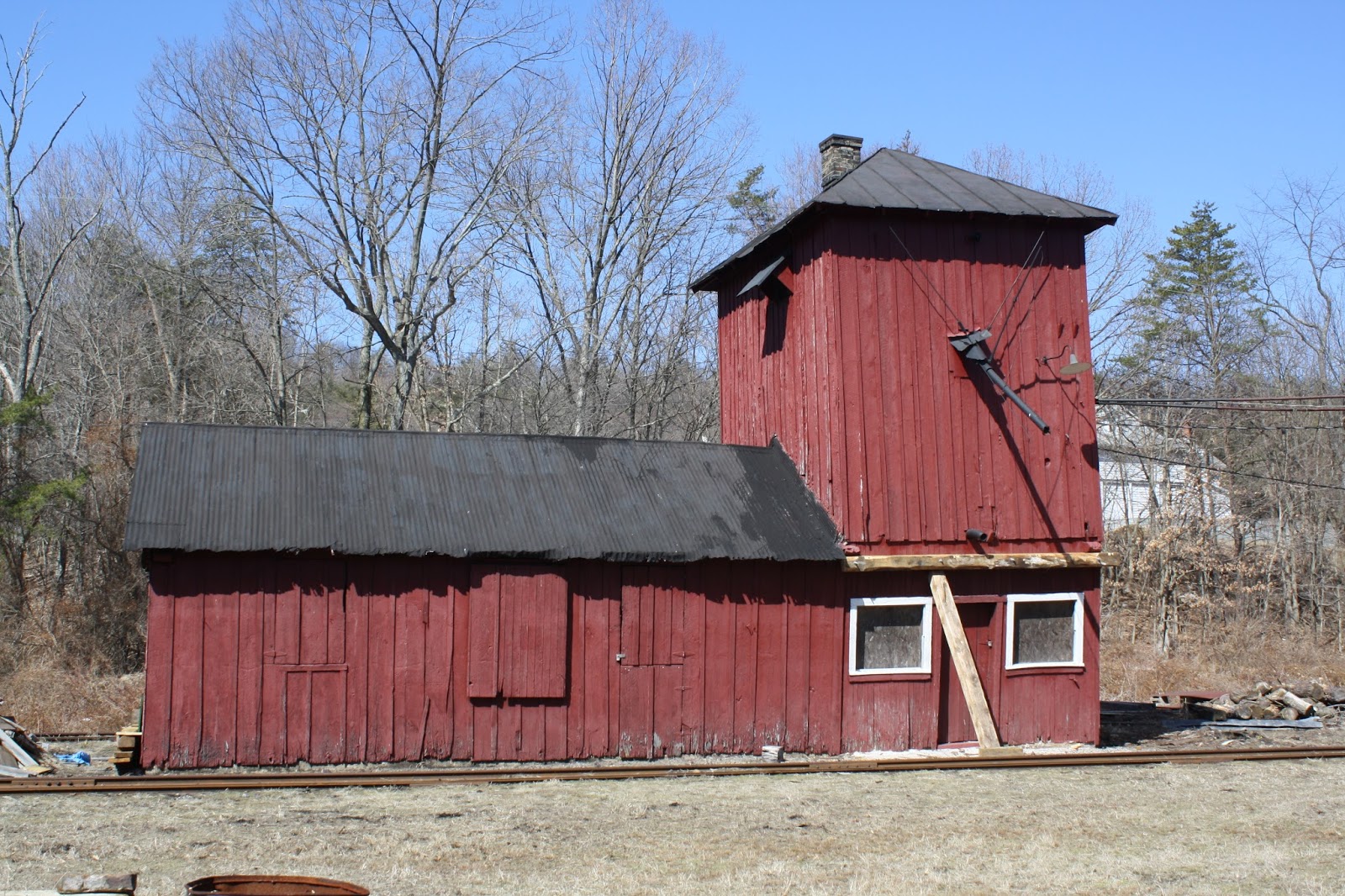
Situated to the west of the locomotive shop is another, less imposing but still interesting structure: the sand house and tower.  Like many other shop buildings, the sand tower had fallen into disrepair and was listing to one side.  The FEBT launched another restoration project, stabilized the buildings, and provided for their structural integrity,


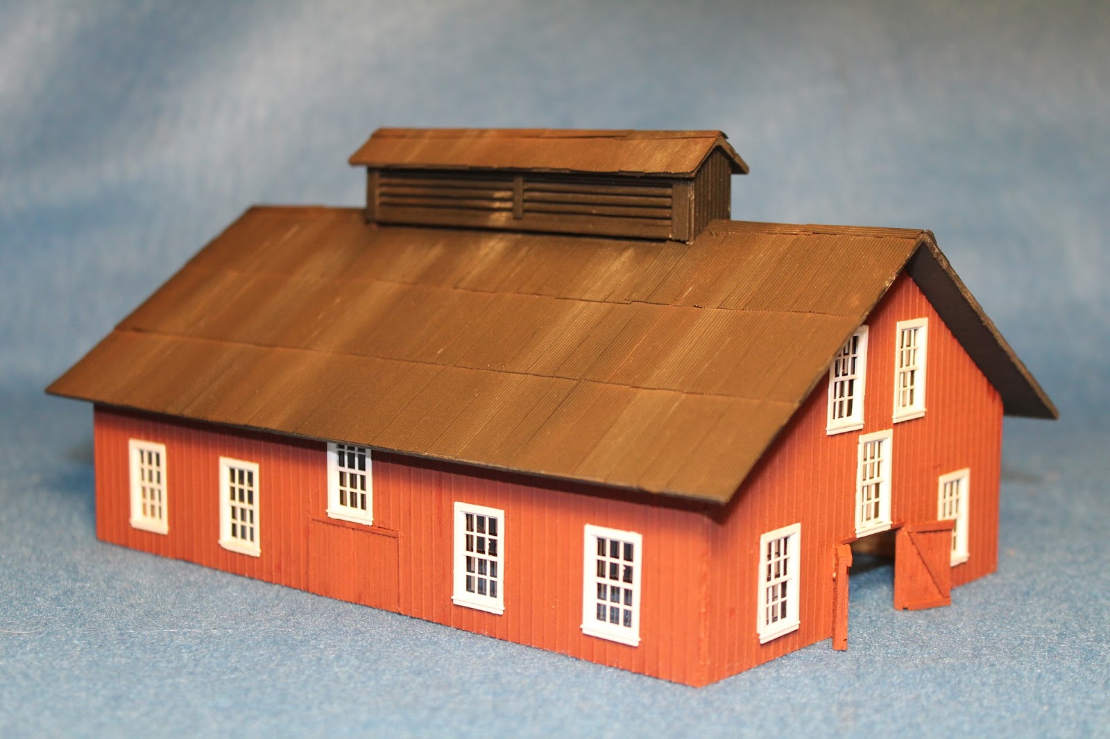
The sand tower was built from another White Ground kit, following the directions in a straightforward manner.  However, when it came to the adjacent sand house, I decided to have some fun and portray it in a weathered and dilapidated condition.  After assembling the walls using the same methods as previously described, I then brushed the board and batten siding with a mixture of 93% isopropyl alcohol and India ink, applying more of the solution to the bottom of the boards, where they would have had more water damage.  I then applied Floquil oxide red paint by pouring a small amount in a flat dish, dabbing it with a cloth, and wiping the paint with gentle downward strokes, applying the paint heavier at the top and fading away to the stained boards at the bottom.  Finally, I brushed a thin layer of Minwax gray stain over the siding.  The edges of the corrugated roof panels were dabbed with Floquil rust to suggest a deterioration of the metal edges.  Here is my version of the sand house and tower.


Much work remains to be done on my shop scene.  Track has been laid and wired, but still needs to be ballasted.  Ground cover, weeds and grass will follow.  The roundhouse is a work in progress.  I still have to finish aligning the tracks and gluing them down, installing lights, and constructing the roof.  But the end is in sight!  I will continue to update work on the Rockhill Shops as it progresses. Thanks for your continued interest and support.

Friday, December 2, 2016

Modeling the EBT Shops - The Paint Shop

In my last post I illustrated how I scratch built the EBT Electrical and Air Brake Shops, an unusual and rarely modeled structure.  In this post I will discuss construction of the EBT Paint Shop, also infrequently modeled.  The paint shop is a relatively new brick building, located next to the turntable and roundhouse.  It is a fairly simple structure, long and narrow, 21 feet wide and 90 feet in length. There are large double doors in both ends and a single personnel door in the middle of the east side.


The paint shop was completed in 1933, a fact confirmed by a circular date stone on the north end.  At one time, painting was done in the unused 8th stall of the roundhouse, the only stall missing a smoke vent and chimney.  The present paint shop replaced an earlier building which was destroyed by fire.


The ;paint shop has doors at both ends, and the plans available from the FEBT show that both doors were approximately 11 feet in height.  However, the plans are wrong, as the 11 foot height would be too low for much of the EBT rolling stock.  A visual inspection of the two ends showed that the doors in the south end were considerably higher than the doors in the north end. When I built the paint shop, I estimated the southern entrance was 14-15 feet in height.


The paint shop is accessed via a spur track which runs along the banks of Jordan Creek behind the sand house and tower.  The west side of the building is supported by a concrete retaining wall, which I did not include in my model.


As can be seen from the photos, the paint shop is made of clean, lightly colored brick, well pointed. I decided to model the prototype with laser cut brick sheets from Monster Modelworks, a relatively new company offering both structure kits and various types of laser cut siding for scratch building.  I selected the "clean" brick siding along with matching corners.

As mentioned above, the paint shop is 90 feet in length, which turned out to be a little too long for the space I had available on the layout.  I decided to shorten the building by one single window at each end, reducing the length to 76 feet while preserving the appearance of the finished structure.  Since the Monster Modelworks brick is available in a 6" by 12" sheet, I determined that one sheet was just enough for the model.

Building the Model

The Monster Modelworks brick sheets have an "up" side stamped on the reverse side.  The 1/8" corners also have an "up" side, so that the sides and the corners can be matched.  The laser cut brick work is neat, precise and very well done.  The panels come with color variations in the unpainted wood that looked so realistic I was tempted to leave them that way!


Using dimensions from the FEBT plans, I laid out Tichy #8056 38" x 92" 9/9 double hung windows on the back of the brick sheet and marked the openings with a sharp pencil.  Using a small chisel blade and hammer I carefully cut out the openings for the windows and the door. The 1/8" thickness helped me avoid accidentally splitting the basswood.  I used a nail file emery board to true up and smooth the openings.  Before gluing the corners to the sides, I test fit the windows and door frame.


Once I was satisfied that the windows were square, the next step was to paint the bricks.  But I was not sure what colors to use,  The walls were not your usual brick red; they had a pale yellowish hue.  I didn't want to use too dark a color, and so I began to experiment with combinations of acrylic paints from the local craft store.   I used the pieces of brick wall I had cut out for the windows to see how different paints appeared.


For a base coat, I experimented with various craft paints labled "adobe" and "yellow ocher" as well as Polly Scale "rust".  Monster Modelworks has additional helpful suggestions for painting the bricks on their website.  My first effort was to brush on a first coat of adobe, then when dry, add overcoats of yellow ochre and rust.   Then I reversed the order and started with ocher and added additional coats of adobe and/or rust.


After trying various colors and techniques, I decided to go with the adobe base coat, which has an orange tinge to it.  Then I applied very small amounts of rust unevenly using a stiff bristle brush.  I dabbed the brush in a small amount of paint, then dabbed it on a paper towel to remove most of the paint.  Then I touched the bricks very lightly with the end of the brush.  I repeated the same process with the yellow ocher, but used it more widely over the wall.  Finally, I highlighted a few bricks here and there with black and off white acrylic.  A close inspection of the paint shop walls will reveal a scattering of these discolored bricks.  In the photo above, the scrap of brick on the bottom right is what I found most appealing.

Having decided on colors, I bit my lip and began to paint the brick walls and corner pieces using the same technique.   Here is the result of my efforts.   I think the colors are reasonably close to the photos of the paint shop above.  Note that the north and south door openings and the personnel door opening have squares of balsa wood glued behind them.  I planned to cut the doors from scribed styrene sheet; the doors would be separately painted and would be glued to the balsa backing.  This is the same technique I used with the electrical shop and air brake shop in my previous post.


My next challenge was to add the mortar lines for the bricks.  Here again I tried various methods using the window and door knockouts for practice.  The Monster Modelworks guidelines on adding mortar to the bricks suggested mixing rubbing alcohol and Bragdon's Lime White Mortar weathering powder, applying it as a thin wash, then drying it with a hair dryer.  Not having Bragdon's powders, I used Dr. Ben's weathering powders purchased from Micro Mark.  Maybe Bragdon's is different, but I was not satisfied with the result.  The wash left a white residue on the surface of the brick.   I also tried a wash of white water color, but all my efforts still left a white residue on the bricks.  Finally, on the suggestion of another modeler I met at the local hobby shop, I drove to Home Depot and bought a $2.00 can  of Durham's Water Putty.  


A very thin mixture of water putty and water was dabbed over the brick wall, then dried with a heat gun on low.  Although there was some residue on the brick surface, it was readily wiped off with a slightly damp cloth or finger.  As the putty dried, the mortar lines gradually appeared, and the result was exactly what I was looking for.  Not only that, but I now have a lifetime supply of Durham's water putty!


With the walls finished, I painted the window frames flat white and installed them in the brick walls. I also glued the corner pieces to the ends of the walls at this time, using Elmer's yellow carpenter's glue.  After painting and adding the double doors and the personnel door, the building was beginning to take shape.  The concrete foundation was also added at this time.


My next step was to glue the walls together, again using yellow carpenter's glue.  I also glued 1/8" square stripwood along the top and bottom of each side and end piece to prevent warping.  


With the walls assembled, the building was beginning to resemble the prototype ... except for the roof.

The north and south doors are heavily weathered in the photographs above.  I applied a small amount of driftwood acrylic paint over the oxide red doors.  The result was a streaked, weathered look that is a good facsimile of the prototype.  The north doors and the personnel door were similarly treated.


The only thing remaining was to complete the roof, using techniques similar to what I did with the electrical shop in the previous post. A cardboard sub-roof was cut from mat board, then corrugated metal panels were cut from Campbell corrugated strips.  There was one final problem, however; in the photos, the roof has a reddish orange color. It was not clear if the roof was painted this color or simply heavily rusted.  Early photos in books on the EBT suggest that it has been this color for many years.   I put out a request for information on the EBT website, but got no replies.  Finally, I decided that since the building is situated a good three feet from the aisle on my layout, no one would be able to tell if the roof was painted or rusty.  So I spray painted the roof the same NATO Black I used on other shop roofs, followed by a heavy coat of Dr. Ben's Rusty Red weathering powder.  The result is close enough to the prototype for my purposes.  


The next and last installment in this series will highlight a number of other shop buildings -- some scratch built, some kit built, some kit bashed -- where I have used techniques similar to those illustrated here to create a unified, realistic version of the EBT shops as they appeared on a summer day in the 1950's.