The town of Mount Union marked the northern terminus of the East Broad Top narrow gauge railroad and its junction with the Pennsylvania Railroad. While Broad Top coal was one reason for the town's importance, it was not the only local industry. Mount Union was also home to three large brickyards, or refractories, where ganister rock (a mineral found in several locations along the EBT) was quarried, crushed, and made into high temperature firebricks for the steel mills of Pittsburgh. In their heyday, North American Refractories (NARCO), General Refractories (GREFCO) and the huge Harbison Walker plant employed thousands of workers and were a primary source of employment for the citizens of Mount Union and the surrounding area.
Here is an early post card view of the Harbison Walker refractory in Mount Union.
The Harbison Walker facility was located at the foot of Jack's Mountain, seen in the background, a major source of ganister rock on both sides of the Juniata River. The huge size of the refractory is best seen from an aerial view. Below you can see the long rows of kilns, where the yellowish bricks were fired at high temperatures, and the associated smoke stacks to vent off the heat and smoke from the fires. In the early days, kilns were fired with coal or coke. Toward the end of its existence, H-W had made the transition to natural gas, which was plentiful, cheap, and less toxic than coal. The tracks in the foreground are dual gauge for the EBT and the PRR.
Across town, North American Refractories, or NARCO, was located on the banks of the Juniata and was served by a spur of the PRR. On the lower left, below, you can see the roofs of standard gauge boxcars in which the newly fired bricks would be shipped out on the Pennsy to steel mills east and west.
When I began to plan my own layout, I knew that I wanted to include a smaller version of these bustling industries. The town of Blacklog, with its dual gauge yard and coal cleaning plant, was modeled after Mount Union. So it seemed reasonable that Blacklog include a brickyard as well. I had explored the hills around the Harbison Walker plant when I lived in Mount Union, and I knew I wanted my brickyard to resemble a miniature version of that facility. I was inspired by a close-up view of the refractory in a photograph provided by the Mount Union Area Historical Society.
I particularly wanted to reproduce the complexity of the brickyard, with conveyors bringing ganister rock down from the quarries on Jack's Mountain, the large crusher to the left center, the kilns and stacks in the background, and the variety of structures, roofs, and building materials in the photograph.
For the crusher, I used a Walther's Glacier Gravel plant kit, 933-3062, which would be connected to quarries on a nearby mountainside by combining several of the Modern Conveyor kits (933-3518). Here you can see the crusher on the left, served by two tracks. The Blacklog Valley main line runs under the conveyor as it loops back around the town. The mountain on the right was made of layers of 2 inch pink foam insulation, stacked to suggest receding terraces from years of quarrying ganister from the mountainside. In the lower right corner is the dual gauge EBT wye.
An Easton Mill building by Railway Design Associates would be added later to provide a place for shaping and preparing the firebricks for the ovens. There would also have to be several large warehouses to hold the finished products for shipment. All of this would need at least five industrial spurs to service the plant. Here I am laying out the brickyard to get a feel for how it might look.
While most of the structures in the refractory were commercially available for kitbashing, I was at a loss as to how to model the kilns. At first I was attracted to the wonderfully detailed resin kilns from Model Railstuff (Walthers 506-660) with massive matching stacks (506-680). But after spending more than $75.00 for one kiln and stack, I started looking for an alternative. After more than a year of searching, I stumbled over a set of cast plaster kilns on eBay from Imported Specialties out of Columbus, Ohio, which were about a third the price of the resin models. The plaster kilns were pure white. The following photo shows one of the kilns after spraying wiyth Model Master 1963 Desert Sand. The paint was as close as I could get to the color of the kilns and stacks at Mount Union.
Apparently, the maker of these kilns no longer exists; but eventually I was able to accumulate a total of six kilns on eBay, some of which had been broken and glued back together. Still, beggars can't be choosers, and I felt that when painted and weathered, the cracks would hardly be noticeable. That turned out to be correct, as you shall see in the next post, when I continue the story of how I built the Blacklog Refractories Company, or BREFCO for short.
Sunday, August 25, 2013
Tuesday, March 26, 2013
Finishing Tori's Trestle
Over the course of five postings I have described how I built and sited a 140 foot curved trestle for my HO gauge Blacklog Valley Railroad. The Blacklog Valley, as you may recall, was originally designed as a bridge route running between Port Royal, Pennsylvania and Hancock, Maryland. The BVRR interchanges with the narrow gauge East Broad Top at Blacklog.
Originally, I had no intention of building a trestle, but two factors induced me to take on the project: First, my youngest granddaughter had asked me to include a "tall, spindly trestle ... with a waterfall .... and an alligator". Second, in preparing for the National Model Railroaders Association achievement certificate in building structures, I had to construct a bridge or trestle. And so the die was cast, and Tori's Trestle became a reality.
Part 5 of this series of articles ended with the making and painting of the plaster rocks that form the backdrop for the trestle.
From this photo you can see where a mountain stream will carve through the hills above the ravine, crashing down into a rocky pool below, and flowing out under the trestle. The next step was to carve out the stream bed under the trestle and line it with plaster. The lining is critically important for the next step, which involved mixing and pouring a two part clear resin call "Magic Water". The resin has a tendency to creep into any hole or crevice unless it is carefully confined.
Above you can see the creek bed where it has been gouged out of the pink foam base, lined with plaster of paris, and colored earth brown for convenience in working with the plaster. I then painted both the upper and lower creek beds with acrylic paints, using several shades of green. The darkest green was used for the deeper places and the lighter shades for the shallows.
With the creek bed painted, I added several small stones to suggest boulders that have broken and fallen off the cliff above the stream. I poured the Magic Water, and then discovered that not only does it creep into holes and crevices, it also creeps up and over small pebbles and rocks in the creek bed! Notice the resin on the sides of the stones.
The effect was even worse for the upper stream, where the rocks were completely covered in resin!
Fortunately, I discovered (serendipitously) that the resin covered rocks can be painted with acrylics. A careful brushing of slate gray acrylic on the rocks left them looking even more realistic than when I started. Phew!
So far, I had a fairly good looking stream at the top and the bottom, separated by 80 feet of vertical cliff. Obviously, I needed a way for the water to get from stream A to stream B -- in other words, a waterfall! I decided to make my waterfall out of DAP 3.0 clear acrylic caulk. The technique is fairly simple. First, a frame is made from a sheet of clear plastic (I used acrylic sheet from Home Depot) cut to size. The upper end of the clear plastic is heated (in my case with a heat gun) until it becomes soft and flexible. It can then be bent to suggest water pouring over the top of the cliff.
Once the clear plastic support is finished, the next step is to construct the rushing water. Beads of caulk are laid out side by side on a sheet of waxed paper using a caulking gun, then mingled together to the proper width with a toothpick, and allowed to dry for at least six hours. Be sure to lay the beads of caulk at least 1/2 inch longer that the height of the waterfall. The caulk is then peeled off the waxed paper and fitted to the clear plastic form. (Be sure to wear latex gloves for this step, in case the caulk isn't completely dry.) If you wish, you can secure the caulk to the plastic with ACC.
The waterfall can then be adjusted to the available space and glued into position with caulk or ACC cement.
But wait! We're not finished yet! We need to add rapids to the rushing waters at the top and bottom of the waterfall. There are several ways to do this. You can use "Water Effects" by Woodland Scenics or you can use a heavy gloss gel from AC Moore or Michael's art departments. I tried both and found little difference between them. The heavy gloss gel seemed to hold peaks better when stippled on the water. Both materials dry clear, so to get the effect of foaming water, I mixed my gel with a small amount of titanium white acrylic paint. The mixture was stippled around the rocks to resemble rushing water.
I also brushed the gel mixture on the falls, especially around the top and then randomly down the length of the waterfall. The key word here is "random".
The finished product is beginning to look like a waterfall!
The addition of some homemade lichen trees makes the scene even more realistic.
Reassured that this fiber stuff would really work, I began to smooth it on over the plaster cloth base under the trestle and up the right hand hillside. I applied a coating of Woodland Scenics blended ground foam over it all. A Noch briar patch was used at the left hand tunnel mouth for scenic interest. At this point I still have to cover the ground under the trestle supports, but here is the result:
We're not quite finished yet. An 80 foot waterfall creates a lot of spray. The bottom of the falls should be clouded in mist. To create the misty effect, I used imitation Halloween cobweb material from my local party store. A small amount teased out over the bottom of the falls gives just the right impression. A brief spray of clear Krylon spray fixed the spray in place and gave it a little sparkle.
To the left of the falls is a small, quiet pool. This would be the natural lair for my granddaughter's beloved alligators. I wanted to highlight the pool with vegetation, using Noch's new laser cut ferns and cattails. These are fun to apply. You just pop them out and fold them together between thumb and forefinger, add a spot of ACC and presto! If you look carefully, you can make out a gator hiding next to a bunch cattails, while its sibling suns on a rock at the foot of the falls.
This concludes my six part series on building Tori's Trestle (and so as not to neglect my youngest grandson, Tucker Falls). I still have some work to do integrating the scene into the rest of the layout. Track remains to be ballasted, and a hardboard fascia strip will eventually frame the scene. But this is what a visitor sees today when entering the train room.
Originally, I had no intention of building a trestle, but two factors induced me to take on the project: First, my youngest granddaughter had asked me to include a "tall, spindly trestle ... with a waterfall .... and an alligator". Second, in preparing for the National Model Railroaders Association achievement certificate in building structures, I had to construct a bridge or trestle. And so the die was cast, and Tori's Trestle became a reality.
Part 5 of this series of articles ended with the making and painting of the plaster rocks that form the backdrop for the trestle.
From this photo you can see where a mountain stream will carve through the hills above the ravine, crashing down into a rocky pool below, and flowing out under the trestle. The next step was to carve out the stream bed under the trestle and line it with plaster. The lining is critically important for the next step, which involved mixing and pouring a two part clear resin call "Magic Water". The resin has a tendency to creep into any hole or crevice unless it is carefully confined.
Above you can see the creek bed where it has been gouged out of the pink foam base, lined with plaster of paris, and colored earth brown for convenience in working with the plaster. I then painted both the upper and lower creek beds with acrylic paints, using several shades of green. The darkest green was used for the deeper places and the lighter shades for the shallows.
With the creek bed painted, I added several small stones to suggest boulders that have broken and fallen off the cliff above the stream. I poured the Magic Water, and then discovered that not only does it creep into holes and crevices, it also creeps up and over small pebbles and rocks in the creek bed! Notice the resin on the sides of the stones.
The effect was even worse for the upper stream, where the rocks were completely covered in resin!
Fortunately, I discovered (serendipitously) that the resin covered rocks can be painted with acrylics. A careful brushing of slate gray acrylic on the rocks left them looking even more realistic than when I started. Phew!
So far, I had a fairly good looking stream at the top and the bottom, separated by 80 feet of vertical cliff. Obviously, I needed a way for the water to get from stream A to stream B -- in other words, a waterfall! I decided to make my waterfall out of DAP 3.0 clear acrylic caulk. The technique is fairly simple. First, a frame is made from a sheet of clear plastic (I used acrylic sheet from Home Depot) cut to size. The upper end of the clear plastic is heated (in my case with a heat gun) until it becomes soft and flexible. It can then be bent to suggest water pouring over the top of the cliff.
Once the clear plastic support is finished, the next step is to construct the rushing water. Beads of caulk are laid out side by side on a sheet of waxed paper using a caulking gun, then mingled together to the proper width with a toothpick, and allowed to dry for at least six hours. Be sure to lay the beads of caulk at least 1/2 inch longer that the height of the waterfall. The caulk is then peeled off the waxed paper and fitted to the clear plastic form. (Be sure to wear latex gloves for this step, in case the caulk isn't completely dry.) If you wish, you can secure the caulk to the plastic with ACC.
The waterfall can then be adjusted to the available space and glued into position with caulk or ACC cement.
But wait! We're not finished yet! We need to add rapids to the rushing waters at the top and bottom of the waterfall. There are several ways to do this. You can use "Water Effects" by Woodland Scenics or you can use a heavy gloss gel from AC Moore or Michael's art departments. I tried both and found little difference between them. The heavy gloss gel seemed to hold peaks better when stippled on the water. Both materials dry clear, so to get the effect of foaming water, I mixed my gel with a small amount of titanium white acrylic paint. The mixture was stippled around the rocks to resemble rushing water.
I also brushed the gel mixture on the falls, especially around the top and then randomly down the length of the waterfall. The key word here is "random".
The finished product is beginning to look like a waterfall!
The rock face and falls look pretty good, but the scenery around them is lacking in .... well, scenery! I planned to use a new product called "Fusion Fiber" for the ground cover. Fusion Fiber resembles Sculptamold, but according to the manufacturer, True Scene, is easier to apply and color. You mix the fibers in a container of water and acrylic paint (I used earth brown) until it forms a squishy mass. The fibers can then be troweled over the base with a putty knife. The major advantage of Fusion Fiber is that no glue is required to add ground foam, clump foliage or even trees. The stuff is sticky when wet. If it dries, just spray with a little water and it becomes flexible again. Here I have applied the fiber to the hill top above the falls, and sprinkled it with several shades of ground foam.
The addition of some homemade lichen trees makes the scene even more realistic.
Reassured that this fiber stuff would really work, I began to smooth it on over the plaster cloth base under the trestle and up the right hand hillside. I applied a coating of Woodland Scenics blended ground foam over it all. A Noch briar patch was used at the left hand tunnel mouth for scenic interest. At this point I still have to cover the ground under the trestle supports, but here is the result:
We're not quite finished yet. An 80 foot waterfall creates a lot of spray. The bottom of the falls should be clouded in mist. To create the misty effect, I used imitation Halloween cobweb material from my local party store. A small amount teased out over the bottom of the falls gives just the right impression. A brief spray of clear Krylon spray fixed the spray in place and gave it a little sparkle.
To the left of the falls is a small, quiet pool. This would be the natural lair for my granddaughter's beloved alligators. I wanted to highlight the pool with vegetation, using Noch's new laser cut ferns and cattails. These are fun to apply. You just pop them out and fold them together between thumb and forefinger, add a spot of ACC and presto! If you look carefully, you can make out a gator hiding next to a bunch cattails, while its sibling suns on a rock at the foot of the falls.
This concludes my six part series on building Tori's Trestle (and so as not to neglect my youngest grandson, Tucker Falls). I still have some work to do integrating the scene into the rest of the layout. Track remains to be ballasted, and a hardboard fascia strip will eventually frame the scene. But this is what a visitor sees today when entering the train room.
Saturday, March 9, 2013
Tori's Trestle - Part 5
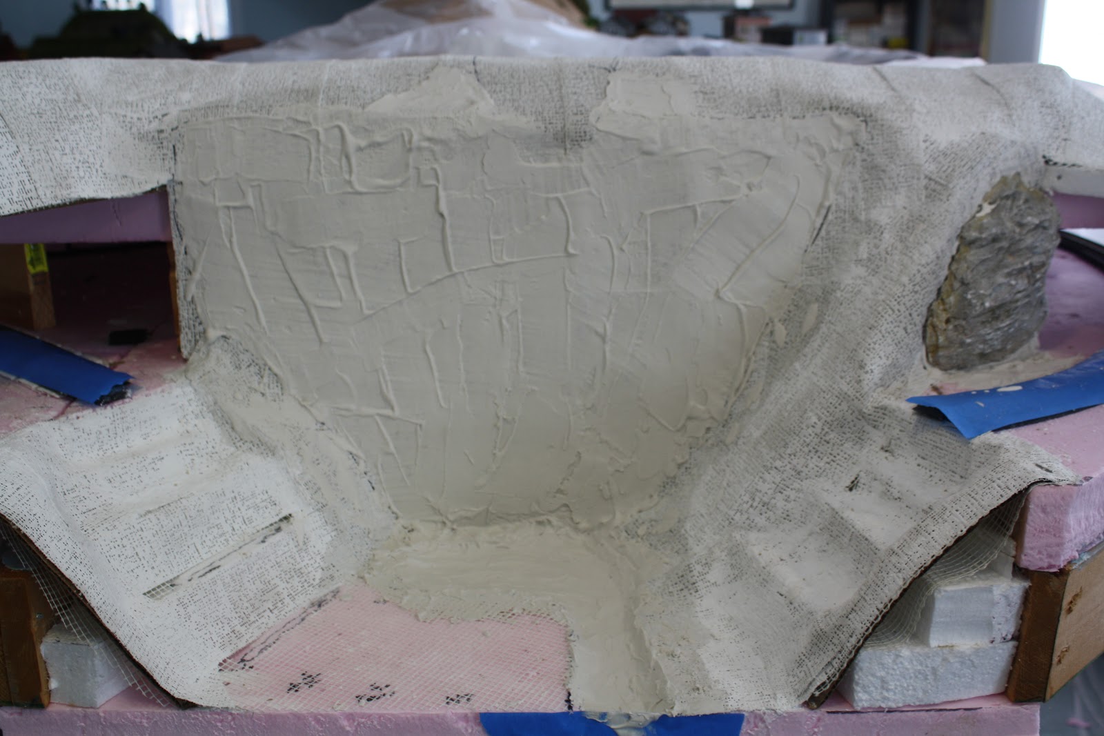
In my previous post, I explained how I carved out the ravine over which Tori's Trestle will pass. The shape of the opening was roughed out with strips of cardboard and the floor of the ravine overlaid with Fiberglas screen to provide "tooth" for the Fusion Fiber scenery base. The next stop was to cover those areas with plaster cloth that will be covered by plaster rocks. Here is a picture of the project before adding the rock wall.
To give a solid support for the large rock castings behind the trestle, the vertical wall was coated with a layer of Hydrocal. The channel for the upper stream that will cascade down the rock wall, and the carved out shape of the pond and rapids below, were also coated with Hydrocal
Once the Hydrocal had set, I began to experiment with positioning the large latex molds that would be used to cast the center of the rock face. Fortunately, the two largest molds fit together reasonably well, and the gap between them could be filled with plaster, then blended together with a knife to give a seamless appearance to the wall. I used Plaster of Paris for the rocks, since it accepts acrylic stains better than the rock hard Hydrocal.
I filled the molds with Plaster of Paris, then waited until the plaster began to set. While the plaster was setting, I sprayed the Hydrocal wall thoroughly with water. This is a critical step, for if the Hydrocal is dry, it will instantly suck the water out of the casting and the rock will not hold. The liquid plaster is ready to apply if it no longer spills out of the mold when you pick up an edge. Then the mold must be lifted gently, supported as much as possible with both hands. The casting is placed on the Hydrocal and held in place by the edges for several minutes until the plaster sets. After ten or fifteen minutes, the mold can be gently removed.
Here is a picture of the rocks with the trestle in place. To give you an idea of the scale of the scene, the trestle is 160 feet long and 40 feet high. The top of the waterfall where it will emerge from the upper stream is 80 feet high. At this point a great deal of work remains to be done on the rock wall. The two castings will be plastered together and the seam shaped with a knife to give the illusion of a single massive granite wall. One of the rocks will be recast and cut into pieces to fill in most of the empty space on either side.
A waterfall has to have a source. I cut out a channel in the hill at the top of the ravine for a stream. The sloping sides of the channel were covered with cardboard and plaster cloth, and a channel was carved out of the foam stream bed. Eventually, the sides will have cast rocks glued to them rather than the flat, artificial sides.
The waterfall cascading over the cliff will be a key feature of the scene. To see how the waterfall would fit in the scene, I used a piece of white paper to gauge where the falls would land, and decided to enlarge the pool at the bottom of the cliff. Impressive!
I decided to stain the rocks using a method called "leopard spotting" that I picked up from the Woodland Scenics website. It's a very simple technique that consists of randomly "spotting" the casting with several different colors of acrylic paint in a water solution. It is much easier to make the rocks darker if the colors are too light, than to lighten them up if the colors are too dark. So I used Forest Green, Slate Gray and Raw Umber in solutions of 1:16 to 1:32. Once the rocks are stained with various colors, the next step is to apply a weak black stain, but to allow it to flow over the rocks rather than spotting them. In this way the black runs down cracks and crevices and gives depth to the casting. Since I was new to the techniqe, I used it on a spare casting to test my technique. I was genuinely amazed how realistic the rocks appeared after this simple technique.
Reassured that I could paint a realistic rock wall, I proceeded to cast another large rock, then cut it in pieces to fill in the voids on the face of the cliff. In the following picture, I have filled in the gaps between the various castings with plaster. A hobby knife and dental tool were used to shape the plaster to make it a part of the adjacent castings.
Now to the exciting part! I mixed solutions of acrylic paint and water, and lightly spotted the rocks with green, brown and gray. Then I dipped my brush in the black solution and allowed the stain to run down the face of the cliff. If the stain did not run into some cracks, I applied it directly. The results were amazing!
When I was satisfied with the results, I stood back to admire my work. A massive rock face now stood where there had been only a flat sheet of Hydrocal. The white spaces on the left and lower right will be filled with vegetation when the scenery is finished.
Once again, I wanted to see what the finished product would look like. Here it is with the trestle in place. In the next installment, I will detail how I made the waterfall and the rapids using simple materials such as acrylic caulk and Woodland Scenics Water Effects.
To give a solid support for the large rock castings behind the trestle, the vertical wall was coated with a layer of Hydrocal. The channel for the upper stream that will cascade down the rock wall, and the carved out shape of the pond and rapids below, were also coated with Hydrocal
Once the Hydrocal had set, I began to experiment with positioning the large latex molds that would be used to cast the center of the rock face. Fortunately, the two largest molds fit together reasonably well, and the gap between them could be filled with plaster, then blended together with a knife to give a seamless appearance to the wall. I used Plaster of Paris for the rocks, since it accepts acrylic stains better than the rock hard Hydrocal.
I filled the molds with Plaster of Paris, then waited until the plaster began to set. While the plaster was setting, I sprayed the Hydrocal wall thoroughly with water. This is a critical step, for if the Hydrocal is dry, it will instantly suck the water out of the casting and the rock will not hold. The liquid plaster is ready to apply if it no longer spills out of the mold when you pick up an edge. Then the mold must be lifted gently, supported as much as possible with both hands. The casting is placed on the Hydrocal and held in place by the edges for several minutes until the plaster sets. After ten or fifteen minutes, the mold can be gently removed.
Here is a picture of the rocks with the trestle in place. To give you an idea of the scale of the scene, the trestle is 160 feet long and 40 feet high. The top of the waterfall where it will emerge from the upper stream is 80 feet high. At this point a great deal of work remains to be done on the rock wall. The two castings will be plastered together and the seam shaped with a knife to give the illusion of a single massive granite wall. One of the rocks will be recast and cut into pieces to fill in most of the empty space on either side.
A waterfall has to have a source. I cut out a channel in the hill at the top of the ravine for a stream. The sloping sides of the channel were covered with cardboard and plaster cloth, and a channel was carved out of the foam stream bed. Eventually, the sides will have cast rocks glued to them rather than the flat, artificial sides.
The waterfall cascading over the cliff will be a key feature of the scene. To see how the waterfall would fit in the scene, I used a piece of white paper to gauge where the falls would land, and decided to enlarge the pool at the bottom of the cliff. Impressive!
I decided to stain the rocks using a method called "leopard spotting" that I picked up from the Woodland Scenics website. It's a very simple technique that consists of randomly "spotting" the casting with several different colors of acrylic paint in a water solution. It is much easier to make the rocks darker if the colors are too light, than to lighten them up if the colors are too dark. So I used Forest Green, Slate Gray and Raw Umber in solutions of 1:16 to 1:32. Once the rocks are stained with various colors, the next step is to apply a weak black stain, but to allow it to flow over the rocks rather than spotting them. In this way the black runs down cracks and crevices and gives depth to the casting. Since I was new to the techniqe, I used it on a spare casting to test my technique. I was genuinely amazed how realistic the rocks appeared after this simple technique.
Reassured that I could paint a realistic rock wall, I proceeded to cast another large rock, then cut it in pieces to fill in the voids on the face of the cliff. In the following picture, I have filled in the gaps between the various castings with plaster. A hobby knife and dental tool were used to shape the plaster to make it a part of the adjacent castings.
Now to the exciting part! I mixed solutions of acrylic paint and water, and lightly spotted the rocks with green, brown and gray. Then I dipped my brush in the black solution and allowed the stain to run down the face of the cliff. If the stain did not run into some cracks, I applied it directly. The results were amazing!
When I was satisfied with the results, I stood back to admire my work. A massive rock face now stood where there had been only a flat sheet of Hydrocal. The white spaces on the left and lower right will be filled with vegetation when the scenery is finished.
Once again, I wanted to see what the finished product would look like. Here it is with the trestle in place. In the next installment, I will detail how I made the waterfall and the rapids using simple materials such as acrylic caulk and Woodland Scenics Water Effects.
Friday, March 8, 2013
Tori's Trestle - Part 4
Over the last three posts, I explained how I went about constructing a 160 foot curved trestle from two Campbell Scale Models kits. But, of course, in the real world bridges and trestles are always built for a reason: Maintaining a constant grade across some sort of depression in the terrain, whether it be a river, a canyon, a swamp, or some other natural barrier. Tori's Trestle needed a reason for existing. My granddaughter had requested a tall trestle with a cliff, a waterfall, and a mountain stream roaring beneath it. (Oh, and an alligator, but that comes later .... much later!)
In the area where the trestle would sit, the HO gauge Blacklog Valley emerges from a tunnel, curves in front of the viewer, and disappears into another tunnel. The trestle was built on a tracing of the curved track that would be replaced by the new structure. In order to situate the trestle on the curve, the tracing was relaid on the 22 inch curve to mark the two ends of the bridge track.
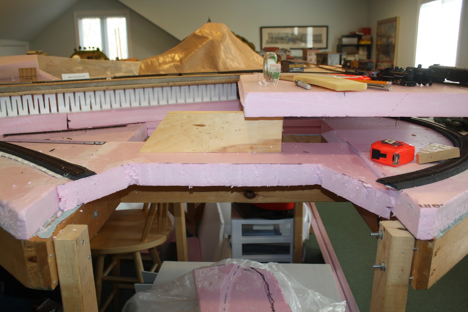
With the track removed, the extruded foam insulation was cut to make space for the ravine that the trestle would cross.
Then the trestle was test fit to the opening to make sure that the rails would meet at either end. A deep sigh of relief followed, when everything fit.
A new foam floor was inserted and leveled such that the railheads on either end line up with the railhead of the bridge track. At last I could begin to see (in my mind's eye) the scene that would eventually fill the empty void before me.
The space behind the trestle would become a sheer rock face with a cascading waterfall crashing into a pool, and a rushing stream passing under the trestle. I began by erecting a carboard "cliff" and test fitting some latex rock molds that I had picked up at the Springfield (Massachusetts) Train Show back in January.
The trestle supports would descend from the original track level to the floor of the ravine via a series of styrofoam steps. The styrofoam was held in place with steel pins.
I checked to see if the trestle bridge track was level or canted to one side or the other. Cardboard shims were used to see what kind of adjustment I would have to make. If you look carefully, you can see a glass bubble sitting on the track to indicate the degree of tilt.
Once I was satisfied that the track was relatively level, I removed the trestle again and began to rough in the shape of the ravine using pieces of corrugated cardboard.
I laid pieces of Fiberglas screen over the cardboard to provide "tooth" for the ground cover that would eventually cover for the scene. I like to use projects like this to test out different methods and materials, and it is my plan to use a new product from True Scene called "Fusion Fiber" as a base for the scenery. The Fusion Fiber needs a porous surface to adhere to, which would be provided by the Fiberglas screen.
At this point, it was time to carve what would become a pool and a stream with rapids at the foot of the cliff, and a cut in the hills above for a torrent of water to pour out and over the rock face. I carved out the areas that would hold the "Magic Water" using a surfoam tool. In the photo above, you can see the where the cut will go in the hill above and the pool and stream below.
Before going further, it was time to test fit the trestle again, to get a sense of how the scene was beginning to come together.
At this point, I began to see the scene taking shape almost like a diorama, neatly framed by the two tunnel portals on either end of the trestle. In the next post, I will explain how I formed and painted the plaster rocks to create the dramatic cliff behind the trestle.
In the area where the trestle would sit, the HO gauge Blacklog Valley emerges from a tunnel, curves in front of the viewer, and disappears into another tunnel. The trestle was built on a tracing of the curved track that would be replaced by the new structure. In order to situate the trestle on the curve, the tracing was relaid on the 22 inch curve to mark the two ends of the bridge track.
A Dremel tool was used to sever both ends of the track that would be replaced by the trestle.With the track removed, the extruded foam insulation was cut to make space for the ravine that the trestle would cross.
Then the trestle was test fit to the opening to make sure that the rails would meet at either end. A deep sigh of relief followed, when everything fit.
A new foam floor was inserted and leveled such that the railheads on either end line up with the railhead of the bridge track. At last I could begin to see (in my mind's eye) the scene that would eventually fill the empty void before me.
The space behind the trestle would become a sheer rock face with a cascading waterfall crashing into a pool, and a rushing stream passing under the trestle. I began by erecting a carboard "cliff" and test fitting some latex rock molds that I had picked up at the Springfield (Massachusetts) Train Show back in January.
The trestle supports would descend from the original track level to the floor of the ravine via a series of styrofoam steps. The styrofoam was held in place with steel pins.
I checked to see if the trestle bridge track was level or canted to one side or the other. Cardboard shims were used to see what kind of adjustment I would have to make. If you look carefully, you can see a glass bubble sitting on the track to indicate the degree of tilt.
Once I was satisfied that the track was relatively level, I removed the trestle again and began to rough in the shape of the ravine using pieces of corrugated cardboard.
I laid pieces of Fiberglas screen over the cardboard to provide "tooth" for the ground cover that would eventually cover for the scene. I like to use projects like this to test out different methods and materials, and it is my plan to use a new product from True Scene called "Fusion Fiber" as a base for the scenery. The Fusion Fiber needs a porous surface to adhere to, which would be provided by the Fiberglas screen.
At this point, it was time to carve what would become a pool and a stream with rapids at the foot of the cliff, and a cut in the hills above for a torrent of water to pour out and over the rock face. I carved out the areas that would hold the "Magic Water" using a surfoam tool. In the photo above, you can see the where the cut will go in the hill above and the pool and stream below.
Before going further, it was time to test fit the trestle again, to get a sense of how the scene was beginning to come together.
At this point, I began to see the scene taking shape almost like a diorama, neatly framed by the two tunnel portals on either end of the trestle. In the next post, I will explain how I formed and painted the plaster rocks to create the dramatic cliff behind the trestle.
Monday, February 4, 2013
Tori's Trestle - Part 3
In Part 2 I explained how I decided to construct Tori's Trestle using ME bridge track rather than hand laying wooden ties. I also described the process of staining and constructing the trestle bents or supports. In Part 3 I will show how I attached the bridge deck and track to the bents. The bents were glued to wooden stringers from the Campbell kit. Prototypically, stringers are constructed of three beams bolted together for strength, to which the deck ties are bolted. For our purposes the stringers had to be cut to the proper length, which depended on the radius of curvature.
The trestle was constructed over a tracing of the rails that would be replaced by the finished structure. Using the kit's template for a 22 inch radius curve, I marked the positions on the curve where the bents would be located. Since the template shows only three bent locations, it was necessary to slide it along the tracing, marking the bent locations for the entire structure. Then I turned the bridge deck upside down, and using the marks I had just made, glued the stringers into position with Pliobond contact cement.
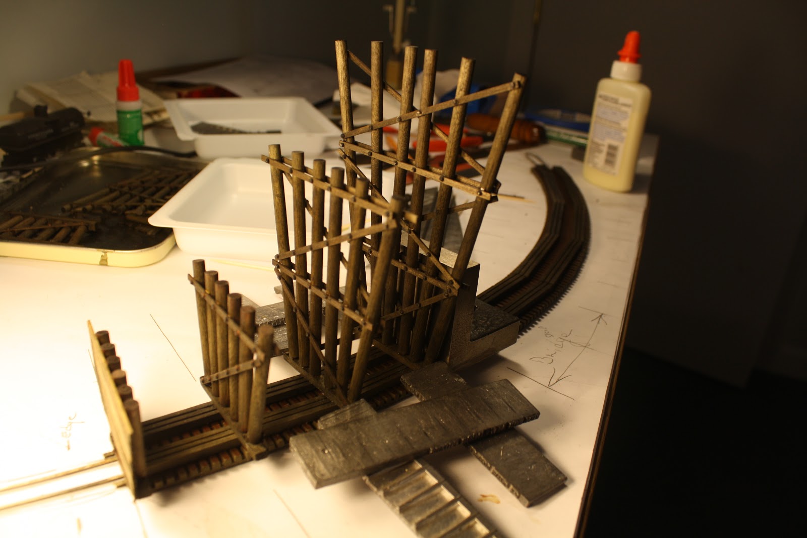
The kit directions called for cutting the stringers to the distance between two bent caps. But prototype trestle construction, particularly on a curved structure, normally has the stringers extend over three bents for added strength. In this next picture, you can see the marks indicating where the bents will be located. Here I am test fitting the first few bents in position on the stringers. The trestle is upside down. The stringers are the grooved wooden pieces to which the bents are glued. One set of stringers runs from the bulkhead to the second bent. The next set of stringers butts agains the first and runs beyond the third bent. You can see where it abuts the next set of stringers. The next bent will fit exactly over the joint between stringers.
Beginning at one end, I glued the bulkhead into position using a machinist's angle plate to insure a 90 degree angle between the stringers and the trestle bent. Lead weights were used to hold the parts in position while the yellow carpenter's glue set.
Here is a view from the other side of the bulkhead. The lead weights were castoffs from an old Linotype press.
Once the bulkhead was fixed, I glued the first trestle bent to the stringers, again using the lines on the tracing to locate and orient the bent.
The process was repeated as each additional bent was glued to the stringers, making sure that the cap was exactly situated over the radius lines drawn from the 22 inch template.
There was no easy way to clamp the bents into position while the glue dried. I used lead weights and a good deal of ingenuity to keep pressure on the bents while also making sure they were at a 90 degree angle to the stringers.
In some cases, applying pressure while the glue dried called for using a variety of objects from around the train room -- for example, here a wooden whistle and a screwdriver serve to keep pressure on one of the longer bents.
When all the bents were firmly glued in place, I gently turned the entire structure right side up to see how it looked. Even without sway braces and longitudinal braces (or girts) one could see the outline of a 160 foot pile trestle on the workbench!
The noticeable empty space in the center of the picture is where the trestle will pass over a mountain stream on the finished layout. In order to allow the structure to bridge the water, a second set of bents was constructed on either side of the gap, to allow four additional stringers to serve as supports for the center of the bridge. This adds a little interest to the structure. Here you can see the stringers in place.
Just for fun, I tried running a car across the still unfinished trestle. What a thrill, after all the work so far, to see the structure working as intended.
Although the bridge looks impressive, it is still very fragile. All that holds the bents to the stringers, and to the bridge deck and rails, is a thin coating of glue where the stringers rest on the bent caps. I found out the hard way how unstable it was when I accidently put too much sideways pressure on one of the bents, and it came off in my hand! Builders of the real thing understood the problem as well, and used a series of cross braces and longitudinal girts to strengthen the trestle.
The girts are simply long pieces of wood that tie the bents together across the length of the trestle. The problem was how to glue them to the piles and apply pressure long enough for the glue to dry. Again, as when glueing the bents to the deck, some ingenuity is required. I used 1/16 inch square stripwood as levers to press the girt to the pile when the glue was applied. Sometimes the levers required a little help from various sizes of wooden clothespins.
It was surprising how much stronger the trestle became with the addition of the longitudinal braces. The final step was to add cross braces on every other pair of bents, following prototype practice. The finishing touches included adding NBW castings where the cross braces were clearly visible to the observer. I did not bother with the back (or concave) side of the trestle, which will face a rock wall and will not be visible from the aisle. A few touch ups with rust and grimy black weathering powders, and the addition of fire barrels and platforms, and the trestle was ready for installation on my layout.
This concludes my description of how I built the curved trestle. The next step, of course, is the installation of the bridge on my layout, including creation of the scenery that will give it life. That will be covered in Part 4.
The trestle was constructed over a tracing of the rails that would be replaced by the finished structure. Using the kit's template for a 22 inch radius curve, I marked the positions on the curve where the bents would be located. Since the template shows only three bent locations, it was necessary to slide it along the tracing, marking the bent locations for the entire structure. Then I turned the bridge deck upside down, and using the marks I had just made, glued the stringers into position with Pliobond contact cement.
The kit directions called for cutting the stringers to the distance between two bent caps. But prototype trestle construction, particularly on a curved structure, normally has the stringers extend over three bents for added strength. In this next picture, you can see the marks indicating where the bents will be located. Here I am test fitting the first few bents in position on the stringers. The trestle is upside down. The stringers are the grooved wooden pieces to which the bents are glued. One set of stringers runs from the bulkhead to the second bent. The next set of stringers butts agains the first and runs beyond the third bent. You can see where it abuts the next set of stringers. The next bent will fit exactly over the joint between stringers.
Beginning at one end, I glued the bulkhead into position using a machinist's angle plate to insure a 90 degree angle between the stringers and the trestle bent. Lead weights were used to hold the parts in position while the yellow carpenter's glue set.
Here is a view from the other side of the bulkhead. The lead weights were castoffs from an old Linotype press.
Once the bulkhead was fixed, I glued the first trestle bent to the stringers, again using the lines on the tracing to locate and orient the bent.
The process was repeated as each additional bent was glued to the stringers, making sure that the cap was exactly situated over the radius lines drawn from the 22 inch template.
There was no easy way to clamp the bents into position while the glue dried. I used lead weights and a good deal of ingenuity to keep pressure on the bents while also making sure they were at a 90 degree angle to the stringers.
In some cases, applying pressure while the glue dried called for using a variety of objects from around the train room -- for example, here a wooden whistle and a screwdriver serve to keep pressure on one of the longer bents.
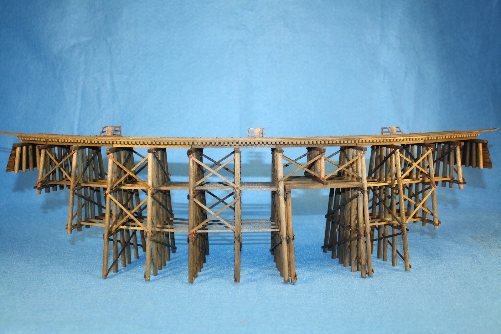
When all the bents were firmly glued in place, I gently turned the entire structure right side up to see how it looked. Even without sway braces and longitudinal braces (or girts) one could see the outline of a 160 foot pile trestle on the workbench!
The noticeable empty space in the center of the picture is where the trestle will pass over a mountain stream on the finished layout. In order to allow the structure to bridge the water, a second set of bents was constructed on either side of the gap, to allow four additional stringers to serve as supports for the center of the bridge. This adds a little interest to the structure. Here you can see the stringers in place.
Just for fun, I tried running a car across the still unfinished trestle. What a thrill, after all the work so far, to see the structure working as intended.
Although the bridge looks impressive, it is still very fragile. All that holds the bents to the stringers, and to the bridge deck and rails, is a thin coating of glue where the stringers rest on the bent caps. I found out the hard way how unstable it was when I accidently put too much sideways pressure on one of the bents, and it came off in my hand! Builders of the real thing understood the problem as well, and used a series of cross braces and longitudinal girts to strengthen the trestle.
The girts are simply long pieces of wood that tie the bents together across the length of the trestle. The problem was how to glue them to the piles and apply pressure long enough for the glue to dry. Again, as when glueing the bents to the deck, some ingenuity is required. I used 1/16 inch square stripwood as levers to press the girt to the pile when the glue was applied. Sometimes the levers required a little help from various sizes of wooden clothespins.
It was surprising how much stronger the trestle became with the addition of the longitudinal braces. The final step was to add cross braces on every other pair of bents, following prototype practice. The finishing touches included adding NBW castings where the cross braces were clearly visible to the observer. I did not bother with the back (or concave) side of the trestle, which will face a rock wall and will not be visible from the aisle. A few touch ups with rust and grimy black weathering powders, and the addition of fire barrels and platforms, and the trestle was ready for installation on my layout.
This concludes my description of how I built the curved trestle. The next step, of course, is the installation of the bridge on my layout, including creation of the scenery that will give it life. That will be covered in Part 4.
Subscribe to:
Posts (Atom)