
My first step was to install the front and rear lights. With the advice and encouragement of Master Model Railroader Laurie McLean in Australia, I opted to use tiny 0606 surface mounted LEDs for the lights. I purchased several of these "SMD" devices, with leads already soldered to the printed circuit board . The diodes are incredibly small, but give off a bright, steady light when voltage is applied. One needs to be careful with the leads, which are a twisted pair of magnet wires, to avoid breaking them or accidently shorting them to the brass shell.
The Hallmark model has a hole already drilled in the back of the headlight fixture. To avoid shorting the SMD to the sides of the headlight, I cut a very small square of paper, made a hole in the center of it, and threaded the SMD leads through the paper. The diode was fixed to the paper with a drop of ACC cement. The hole in the back of the lamp was enlarged so that a length of shrink tubing could be inserted and glued to the back of the paper/diode with ACC. The tubing was then glued to the roof of the M-1 (above the motor) with ACC. The magnet wires were stripped where they emerge from the tubing by dipping each wire in a drop of hot solder. Then the magnet wires were soldered to blue and white #36 stranded wire. The white and blue wires go to the decoder blue and white leads. A 1.2 K resistor was soldered to the blue, or common lead. This is a photo of the headlight assembly.

And this is a view of the front with the SMD installed. You can see the small square of typing paper that holds the diode.

The rear light was a little trickier, since the housing is much smaller than the headlight, not much larger than the SMD. I tried using a small piece of paper, but diode kept shorting against the metal housing. Finally, I decided to force the SMD into a small diameter piece of shrink tubing so that the diode was completely surrounded by insulation. The tubing was just small enough to force into the light housing. A slightly smaller piece of tubing was cemented to the back of the assembly, so that both diode and leads were fully insulated from the shell. The SMD was then tested with an LED tester to make sure it was still working after all that pushing and squeezing. Fortunately, it was.

The rear light was harder to install because of two interior walls separating the rear vestibule from the passenger compartment, and the passenger area from the baggage section. Fortunately, there were doors in both partitions, and the wires were threaded through the open door windows to the space which would hold the decoder. The SMDs give off a bright white light. In order to soften and diffuse the light, I mixed a small amount of Tamiya X24 clear yellow paint with some Canopy glue. The glue dries clear, and mixed with the paint gives the diode a soft yellow light that seems appealing to me. I also filled the headlight fixture with the glue/paint mix. When dry it gives the illusion of a lens covering the light. The rear SMD received a drop of the Tamiya glue as well.
With the headlight and backup light wired, I turned next to installing a 20 mm high bass speaker for sound. At first, I tried to squeeze the speaker next to the decoder just behind the can motor, but there was simply not enough space. The alternative was to install it in the rear passenger compartment, which would allow the sound to exit through the hole in the floor where the rear truck is mounted, as well as through the rear door window. There was plenty of space for the speaker, but the access hole above the truck had to be enlarged in order to insert the speaker. The speaker was secured with Goo to the floor of the coach. Wires were threaded through the forward door window into the baggage compartment, and connected to the sound decoder.

The final step was to install wipers on the front and rear trucks for all-wheel pickup. While the M-1 ran well enough using the left front truck wheels and right rear truck wheels, any dirt or interruption on the track tends to cause a momentary loss of power, causing the sound and lights to reset. All wheel pickup has eliminated almost all of these momentary interruptions. Here is the rear truck showing the red and black power wires to the decoder. One wire is drawn through the kingpost via a wire soldered to a brass washer. The other wire connects to a small piece of PC board cemented to the truck with Walther's Goo. A short length of .01 brass wire is soldered to the PC board, and serves as a wiper for the wheels on that side of the truck.

Wipers were also installed on the front truck, a someone trickier project, requiring the removal of the can motor in order to drop the truck from the frame. The process for constructing the wipers and mount was essentially the same as for the rear truck.

With speaker, lights, and wipers installed, all that remained was to connect the respective wires to the Tsunami decoder, slide the decoder into the space behind the can motor, and reassemble the model. Here is the bottom of the M-1 with all wires in place, ready to assemble.

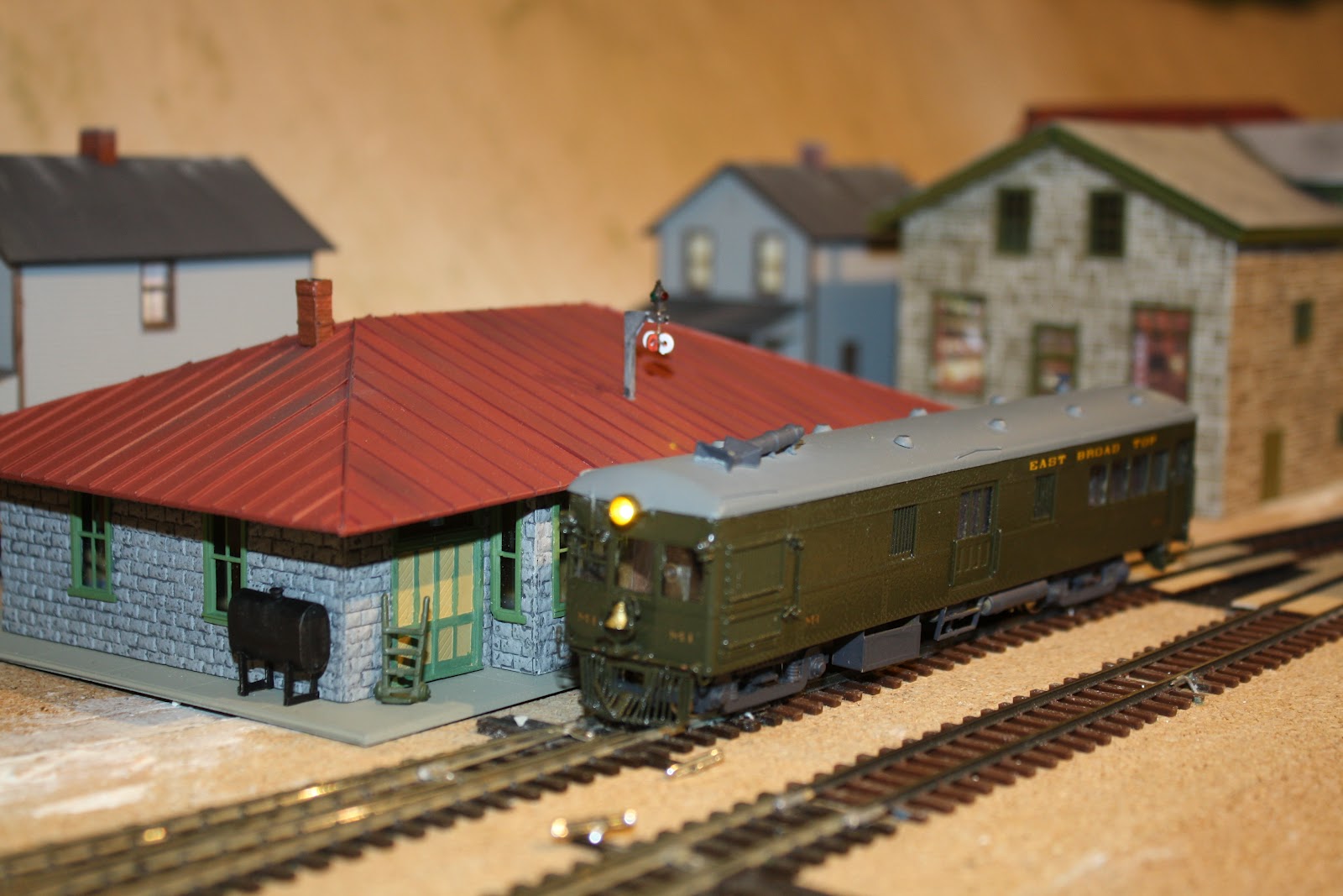
Of course, the proof (as the saying goes) is in the pudding, and I held my breath before powering up the NCE Power Pro system. To my delight, the 244 prime mover sputtered to life, the lights came on, and the M-1 chugged around the layout from the dual gauge Blacklog yard, past the EBT shops at Rockhill, finally coming to a stop at the EBT station in Robertsdale, where these pictures were taken.

This was my second sound decoder installation, and I am beginning to get the knack of it. That's a good thing, as I still have three EBT 2-8-2 mikados (16, 17 and 18) to paint and install DCC. And believe me, if an old coot like me can learn to do this, anyone can! The results are a delight to both the eye and the ear. Try it, you'll like it!