Wednesday, December 2, 2015

Installing an Econami Decoder in the Mantua 0-6-0

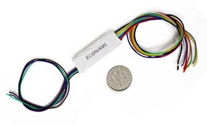
In my last post I explained how I replaced the Pittman open frame motor in my Mantua 0-6-0 switcher, in my conversion of the engine to EBT standard gauge no. 3.  With the motor in place, the next step was to install a digital decoder in the tender.  I opted for a new Econami ECO-100 sound decoder from Soundtraxx, partly because of its small size, and partly because of its new features, which include a large selection of bells, whistles and other sound effects.
The Mantua slope back tender has plenty of room for a decoder and speaker, but I also wanted to install one of the Soundtraxx Current Keepers, a capacitor array designed to keep the motor and sound operating for short periods when power is interrupted, as for instance over switch frogs and dirty spots on the track.


The Current Keeper is somewhat larger than the Econami 100, but there was still plenty of space in the tender for the various components.  I decided to mount the sugar cube size speaker under the coal pile, with holes drilled in the coal to allow the sound to escape.  Here you can just make out the holes on the coal pile.


The sugar cube speakers are very powerful 8 ohm devices originally designed for smart phones, but they are perfect for those tight places on smaller scale locomotives.


The key to obtaining maximum sound from any speaker is the enclosure.  Sound is created by the vibration of a thin metallic membrane, which moves the air around it.  The membrane moves the air on both sides, creating sound waves on the front and the back of the speaker.  But the sound waves from the front and the back are 180 degrees out of phase.  To prevent the sound from one side of the speaker from cancelling out the waves from the other side, the speaker must be fitted to some sort of container that prevents sound waves from escaping both sides at once.  Here I have shown a speaker with a wooden enclosure that fits tightly around the back of the speaker.  Enclosures can be made from virtually any material, from wood to styrene or even paper!  The following picture shows the speaker mounted in the enclosure, ready for installation.  I have not yet connected wires to the speaker terminals in this view.


In the next photo, the speaker has been mounted in the tender, facing up, and secured with a piece of green masking tape.  The Econami decoder lies on top of the back of the speaker, its wires separated with clothes pins to make wiring easier.


Here is a closer look at the arrangement of wires.  Since I did not intend to add special effects lighting other than the headlight, extra function wires were coiled and wrapped with a strip of blue masking tape.  The Current Keeper has not yet been installed.


In the following photo, the decoder has been hard wired into place,  The Current Keeper is the long purple device next to the white Econami.  The wires going to the locomotive include the white lead to the LED headlight.  The other headlight wire was connected to the engine shell, eliminating the need for a blue common line to the decoder.  The other wires between engine and tender are the orange and gray motor leads and a red wire, which is connected to the frame of the engine for track power from the engineer's side.


The long black wire hanging free from the tender is for track power from the fireman's side of the tender trucks.  The Mantua tender was designed to channel track power from the wheels, through the trucks, to the floor of the tender.  To ensure a solid contact between the rail and the decoder, I decided to install wipers to the left side tender wheels, and not rely on the axles to carry the power.I made the wipers by soldering a short length of .01" phosphor bronze wire to a small square of printed circuit board, as shown below.


A length of #36 wire was also soldered to the PC board, and channeled through a hole in the bottom of the tender floor.  Wires from each of the two trucks were connected to the black wire from the decoder by screwing them together to the floor of the tender.  I bored a hole, then tapped for a 2-56 screw to provide  power  from the tender.


Here is a view of the finished product.  The 1.2K resistor is in the headlight circuit.  The light is still too bright for my taste, so I plan either to replace the resistor with a higher value or reduce the current to the LED by adjusting the lighting CV on the Econami.  If you have a sharp eye, you may also notice a piece of blue tape near the front of the tender.  Just to be safe, I installed a solid state fuse to protect the decoder from a power surge to the motor.  Once I decided to replace the open frame motor with a Sagami can motor, the danger of such a surge was eliminated, but I left the fuse in anyway.


After successfully testing the decoder on my workbench, I closed up the tender and tried running the engine on the layout.  Once I was comfortable with the operation, the next step was to program the decoder CVs for the specific sounds I wanted on EBT #3.  A future post will include programming and weathering the engine and installing the standard and narrow gauge couplers on the tender,

Monday, November 23, 2015

Remotoring a Mantua 0-6-0

My first thought in converting the Mantua switcher to EBT no. 3 was to leave the Pittman open frame motor in it.  But would it work?  I wanted to convert the 0-6-0 to DCC.  I had never tried using DCC on a Pittman motor.  I contacted Wayne Weiss, better known as the "Loco Doc", who said the main problem in using an open frame motor is to isolate it from the frame of the locomotive.  DCC motors must be insulated from the engine.  Wayne suggested the simple fix of slipping a piece of insulation around the spring wire that holds the motor brush in place.  One brush is isolated, the other gets power from the wheels and frame of the engine.  This is the brush that must be isolated.  I tried this trick, and it did work ... sort of.  The motor was indeed insulated from the locomotive frame; but I found that the thickness of the insulation forced the brush tighter against the rotor, leading to problems when I tried DCC.


After tinkering with the open frame motor for a week or so, I was able to run the engine back and forth on my yard tracks, but it ran slow in forward and took off like a rabbit in reverse. Also, I could not get the DCC chuff rate to coordinate with the rotation of the drivers.   Digging through my scrap box, I found a couple more Mantua engines, and tried replacing the open frame motor in EBT no. 3 with one from another 0-6-0.  But the problems persisted.  Finally, I had to admit defeat. The only practical solution was to replace the Pittman motor with a good can motor.  Fortunately, I had a 16 x 20 mm NWSL Sagami can motor on hand, which seemed to fit the available space in the Mantua engine.  All I had to do was replace the open frame motor with the Sagami.

Easier said than done!  The Mantua motor turned a nylon worm, which engaged with a nylon worm gear on the main axle, driving the engine.  The simplest solution was to remove the worm from the motor shaft and place it on the can motor shaft.  But  here's where it got interesting.  The worm sat on 2.3 mm shaft; the Sagami motor shaft was only 1.5 mm.  Not only did I have to remove the worm from the old motor, I had to install it on a motor with a smaller diameter shaft.

Not having any experience with this, I contacted NWSL via email and sought the advice of their technical department.  I learned that I would have to use a wheel puller to remove the worm from the old motor shaft, then insert bushings into the worm that would allow it to slip on to the can motor shaft.  The good folks at NWSL told me that once the worm was in place, Loktite super glue couild be applied to the bushings, which when dry would hold the worm firmly in place.

First challenge.  I didn't own a wheel puller.  But NWSL sells them in several sizes, so I ordered one. When it arrived in the mail, I set up the device to hold the worm in place while a screw pressed the shaft, pushing it through the worm. 


The miniature piston pushed completely through the worm, forcing the motor shaft out the other end.


I was able to twist the worm off the wheel puller with little effort.  Say, a guy could get used to this! (Remember, I had never tried to replace a motor before.  The biggest problem was getting the courage up to try.  Once you do, it's surprisingly easy!)


Step two was placing the worm on the can motor shaft.  I had ordered a pair of NWSL bushings with an ID of 1.5 mm and an OD of 2.4.  I tested the bushings on the can motor.  They slipped on easily -- maybe a bit TOO easily!  But another email from NWSL revealed the bushings are made to slide on the shaft, allowing for easy adjustment before bonding them in place.


Although the bushings slid on to the can motor shaft easily, the same could not be said for the worm! Inserting the bushings into each end of the worm proved to be a challenge.  They were so small, and even after chamfering the edges gently with a fine file, they just did not want to go into the worm.


At this point, I used a different tool to simplify the job -- a Precision Arbor Press from Micro Mark that I picked up at a hobby show a few years ago.  The Press-It does the reverse of the wheel puller. It pushes small parts together.  I mounted the worm in the press and carefully centered the punch over a bushing.  To keep the punch and bushing from slipping, I placed a small steel ruler between them and applied pressure.  Pop!  The bushing slipped snugly into the worm.  I repeated the process at the other end, with equally good results.


The bushings were tight in the worm, allowing the whole assembly to slide easily on to the motor shaft.  I carefully applied Loktite to both bushings and let them dry for 24 hours to make sure the bond was secure.

The last step in remotoring was to place the motor on the engine frame so that the worm engaged the worm gear properly.  But the motor has to be isolated from the frame electrically.  Again, the folks at NWSL were helpful guides.  They recommended securing the motor to the frame with silicone -- with Permatex Ultra-Black Gasket Maker to be precise.  When it cures, the silicone is a permanent bond which both insulates and secures the motor.  The rubber-like silicone also reduces vibration. Following the advice from NWSL, I placed a blob of silicone on the engine frame, so that the motor would tilt at the same angle as the open frame motor, allowing the gears to mesh.  NWSL also recommended inserting a piece of .008" brass wire between the worm and the worm gear to allow space for the gears to move when the silicone set.

This turned out to be easier said than done (again!)  The silicone goo was soupy when it came from the tube, and couldn't provide support for the motor, which kept falling flat into the Permatex.  The wire kept slipping out from between the worm and gear teeth.  It took some time and some effort to figure out how to hold the motor in place while the silicone stiffened.


I ended up holding the worm and worm gear in place with my finger until the silicone began to set up.  I also used a small clothespin to prop up the motor shaft.  Some experimentation was required to get the right angle.  I let the silicone set for 48 hours before playing with the motor.  By then the Sagami seemed tightly bonded to the frame, and the motor was safely insulated.


When the bond was secure, I tried running the motor.  The entire engine began to shake and vibrate, then stopped altogether.  A careful examination revealed that the silicone goo had run down the side of the frame and bonded with the rear driver.  Fortinately, the rubbery material is easy to cut with a hobby knife.  A little cutting and cleaning released the driver and allowed the engine to move.  The following brief You Tube video shows the engine operating on my layout.  (Rivet counters will notice that the valve gear is incorrect.  That will be fixed when the project is completed.)


The next installment in this series will detail how I installed and programmed a SoundTraxx Econami decoder in the tender, with "sugar cube" speaker and keep alive.  

Sunday, November 22, 2015

Converting a Mantua 0-6-0 to EBT Number 3: Introduction

The East Broad Top was a 3 foot narrow gauge railroad that ran from Mount Union to the coal fields on Broad Top Mountain in southern Huntingdon County, Pennsylvania.  When the railroad ended common carrier operations in 1956, they owned six narrow gauge steam engines, along with two standard gauge 0-6-0 switchers stationed in Mount Union: Numbers 3 and 6.  Ironically, number 6 was the older engine, built by Baldwin in 1907 and seldom used in the 1950s.  It was the smaller of the two, with 48 inch drivers, 17x24 cylinders, weighing 84,200 pounds with a tractive effort of 19,600.  Number 6 was sold to the Whitewater Valley Railroad in 1975, where it remains to this day.

The other standard gauge switcher was number 3, also a Baldwin, built in 1923.  Number 3 was a heavier engine by far, with 51 inch drivers and 21x26 cylinders.  It weighed in at 137,000 pounds and produced a tractive force of 33,500.  It is currently stored inoperable in the Mount Union engine house.  Both nos. 3 and 6 were equipped with standard and narrow gauge couplers for operating in the dual gauge Mount Union yard.


To my knowledge, there has never been a commercial model of either engine, although an article by Dean Mellander appeared in the December 1990 issue of Railroad Model Craftsman describing how he built a model of EBT no. 6 by kitbashing an MDC Roundhouse 0-6-0 kit.

I have long wanted to include a working model of one or both switchers, to add to the realism of my own dual gauge yard, a compressed version of the one at Mount Union.  After reading Mellander's article, I thought of perhaps using the MDC 0-6-0 to represent no. 6, and even went so far as to acquire a kit.  Yet since no. 6 was rarely used in the era I model (around 1950) it seemed preferable to create a model of number 3.  But I was at a loss as to where to start.

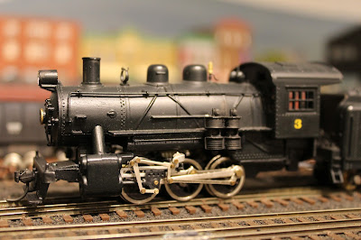
A few years ago, I saw a modified Mantua 0-6-0 on eBay that had been painted to represent no. 3.  It was not an identical copy, as can be seen from the following photograph.  But it was "close enough" for my purposes, since it would operate in the background much of the time, and my focus was on the EBT narrow gauge 2-8-2 mikados anyway.


A quick comparison with the preceding photo reveals immediately some glaring differences between the two.  Most obvious is the fact that the Mantua engine has only one sand dome while no. 3 had two.  This suggests that the prototype also had a longer boiler.  There are also differences in the cab, and the cylinders on no. 3 are considerably larger than the model.  But again, I invoked the modeler's Rule Number One ("it's my railroad") and decided to purchase the Mantua engine and see what I could do with it.

In future posts, I will detail how I converted the open frame Pittman motor to a Sagami can motor, removed the worm from the old motor shaft and installed in on the can motor shaft, mounted the new motor and worm using silicone adhesive, installed an LED headlight and put a new SoundTraxx Econami sound decoder in the tender.  All this has proven to be a learning experience for me, and I am looking forward to sharing the story of how I did it.

Thursday, October 15, 2015

East Broad Top Annual Reunion 2015

Columbus Day weekend the Friends of the East Broad Top (FEBT) gathered for their annual fall Reunion in Rockhill Furnace, Pennsylvania.  This was my first Reunion, and I was looking forward to spending a few days exploring the railroad and meeting some of the people who have worked hard to preserve this unique narrow gauge railroad.  I made arrangements to stay at Pogue Station, an old farmhouse and general store that once served as a flag stop for miners on their way to the coal mines on Broad Top Mountain.


Pogue was the first stop after Orbisonia Station and only a few minutes from the main shop complex in Rockhill.  Just north of Pogue Station, the EBT crossed Aughwick Creek on the longest bridge on the railroad.  Pogue Trestle hasn't seen a train since the early 1960's, but the steel span was still impressive.


After a grueling 10 hour trip from Cape Cod to south central Pennsylvania, I finally arrived and registered at Reunion central in the local elementary school, just across the tracks from the EBT shops and the Railways to Yesterday trolley museum.  Some eighty EBT supporters gathered for a presentation by Lee Rainey on the role of iron mining and smelting in the early history of the railroad.  Rainey, author of the definitive book on the East Broad Top, explained how the railroad was originally founded to serve the Rockhill iron furnaces and coke ovens, the ruins of which can still be found in Blacklog Narrows, just east of the shops.  


Saturday morning, I arrived early and spent an hour or so photographing the Rockhill yard in the bright but chilly morning light.  The Friends of the East Broad Top, led by President Lee Rainey, have worked long and hard to preserve the hundred year old shops and roundhouse.  Without the FEBT, many of the historic structures would have long since fallen down or collapsed.


One of the highlights of the weekend was a walking tour of the Rockhill restoration projects.  We met near the Blacksmith Shop, which has recently been stabilized and painted.  The building had been in danger of collapse prior to the restoration.


After an overview of recent restoration work, the group explored the interior of the foundry, where scrap iron was melted down and cast into parts for the railroad.  The foundry is dominated by a huge 360 degree crane.  While much work remains to be done on the interior, the exterior looks much as it did in 1956.


The group then walked to the south end of the engine shop, where Bill Adams showed the group some of the work continuing on restoration of the shop doors.  The FEBT is building exact reproductions of the existing doors, which were in very bad shape.


Right next to the door project, FEBT members could see the work that has been done on the car shop. One of the iconic photos of the shops shows a stack of locomotive tires leaning against the wall of the car shop.  Unfortunately, the weight of the tires had caused the entire wall of the building to lean as well!  Volunteers working by hand moved the tires away from the walls so they could be braced and strengthened.


Another major project involved the roof of the car shop.  Decades of rain, snow and neglect had rusted the corrugated panels and rotted the beams beneath, so that if a person stepped on the roof, he would go right through!  Standing next to piles of debris, we looked up at a shiny new metal roof that will continue to protect the car shop for years to come.


The restoration tour ended at the paint shop, which is used by the FEBT for a variety of projects. Currently it houses 1890's combine number 14, which was used as a caboose on coal trains in the last years of EBT common carrier operation.  The crews found the combine more comfortable than the two cabooses that are currently stored in the car shop.  Skilled FEBT craftsmen have removed rotted wood from the sides, the roof and the interior, and are hand crafting replacements.


Work is proceeding well, but the car may never roll again.  The wooden trucks that once supported the combine are in dire need of rebuilding, including replacement wheels.  Unfortunately, the cost of replacing the trucks is prohibitive, and neither the railroad nor the FEBT has the funds.  The FEBT will continue work on the car, but its future remains in doubt.


None of the six steam engines were operating for the weekend.  In fact, the EBT has not had a locomotive under steam since 2012.  The M-1 gas electric car is operational, but was not available for the Reunion.  Instead, FEBT members were invited to ride one of three speeders (sometimes called "put puts") from the yard complex to the southern end of useable track, about a twenty minute round trip.  The speeder rides were very popular.  My first ride was the M-3, a 1920's era Nash vehicle that was restored by the FEBT several years ago.


Speeders left the vicinity of the roundhouse and proceeded south past the machine shop, locomotive shop and sand tower, to where a three way stub switch offered access to the main line.  Passing the concrete coal dock and water column, the speeders passed two small sheds that were the first buildings restored by the FEBT.  More recently, the organization has done restoration dock on the coal dock and water supply.


In addition to the M-3, two other small open speeders, once used by track crews, carried passengers back and forth throughout the day.

at 


Saturday afternoon included an open house at the shops and roundhouse, with key members of the FEBT available for questions.  I opted to visit the roundhouse first, where the EBT's stable of Baldwin 2-8-2 Mikados are stored next to the M-1 gas electric.  The roundhouse has eight stalls.  The group was free to explore around the locomotives, some of which have not moved since 1956. The engine most recently under steam is #15, which lacks only an FRA inspection to operate.  Others that have operated in the tourist era include 12, 14 and 17.


FEBT President Lee Rainey was on hand to answer questions about the past, present and future of the railroad.


From the roundhouse, it was a short walk to the shops, where a small group wandered through the various work areas.  The afternoon sun filtering through dusty windows illuminated machines and tools still sitting exactly where they were when the railroad closed in 1956.


Everything was as if the employees expected to return in a few days and work would pick up where they left off.  But they never came back and today the shops are a perfectly preserved museum of the age of steam.


Huge lathes, drill presses and other machines were all drived by an elaborate network of belts and pulleys powered by twin boilers and a steam engine that has been restored to run on compressed air by the FEBT "boiler rats", as they like to call themselves.


Following the speeder rides and the tours, the group reassembled in the elementary school for a presentation by Peter and Jane Clarke on modeling the ganister rock and pig iron industries on their model railroad, featured in the latest issue of Great Model Railroads by Kalmbach Press.  We then proceeded to the trolley museum next door for a ham and green bean dinner to cap off the day. Following dinner winners of the photo and modeling contest were announced.  To my surprise (this was, after all, my very first reunion) I was awarded first prize for structures and a new category called "what if".  I had submitted several vehicles suggesting what the short-lived EBT Transit Company might have looked like if the company had continued into the 1950's.  There were many entries, many of them outstanding, so it was an honor to be included among those recognized for their modeling.


The evening wrapped up with a ride on a Metro Liner operated by Railways to Yesterday and a fund raiser auction back at the elementary school.  That concluded the organized events.  But the Reunion continued on Sunday with an open house at the FEBT museums in Robertsdale along with visits to various model railroads in the area.  I had scratch built the well-known structures in Robertsdale's "company square", but this was the first opportunity to see the prototype builds as they are today: the Robertsdale station, the old post office and the Rockhill Iron and Coal Company office building.  The fourth structure in company square -- the company store -- was torn down in the 1990's.


While touring the museum in the old post office building, I ran into two people who probably know more than anyone else about the coal mining operations on the Broad Top: Ron Pearson, who has published numerous articles in the FEBT journal, the Timber Transfer, and Ric Case, who together with Ron has explored the nine mines and surrounding area served by the East Broad Top Railroad.

Ron pointed out that from the Robertsdale station, one could see the remains of mine number 1.  He and Ric invited several of us to join them in exploring the ruins.  As we walked along the old EBT main line towards Woodvale (the end of the line) Ric pointed out the rotted posts that had supported the tipple for Mine Number 1.


Ron explained how the mines were operated by cables, powered by a steam winch, that pulled loaded coal cars from the mine while simultaneously lowering empties back into the mine to be filled again. Miners were expected to fill the dump cars with a minimum of 2100 pounds of coal; anything less than 2100 pounds and the miner would not be paid!  Each miner was expected to fill 16 cars a day; hence the song by Tennessee Ernie Ford: Sixteen Tons.


As we tramped through the brush and brambles, Ron and Ric pointed out traces of the now long-gone mines -- the foundations of the steam winches, the boilers for the stationary engines, the fences for the mule barn (underground carts were hauled by mules).


At one point we found the remains of a fan house that circulated air in the mine still standing.  The structure was the prototype for an identical fan house now available in HO scale!


Tramping through the woods and seeing the decaying remains of the railroad and mines, I began to realize more clearly how intertwined they were: the mines depended on the railroad, and the railroad would not exist were it not for the mines.  When the demand for Broad Top coal dwindled, the EBT's days were numbered.  Were it not for its surprising return as a tourist attraction, little would remain today.  As it is, by extraordinary good luck and the help of the Kovalchik family (who bought the entire railroad in 1956) all of this history would be lost in the mists of time.  We are so fortunate to have had the EBT for nearly 60 years after it ceased to operate as a common carrier.  Hopefully, a way will be found to preserve the railroad and its history for generations yet to come.