Thursday, December 29, 2011

What Lies Down the Road?

The beginning of a New Year is a good time for looking back and looking ahead.  The news channels are full of retrospectives about what happened in 2011 and what we might expect in 2012.  The same might be said for the Blacklog Valley and East Broad Top Railroads.  Looking back I can see some real progress over the last twelve months.  I now have the EBT mainline complete from Blacklog to Robertsdale with a return track that allows running trains in a loop.  But I can also operate point to point, with the completion of a narrow gauge wye at Robertsdale and a dual gauge wye at Blacklog.  It was also exciting to see ballast and scenery begin to go down around the Blacklog dual gauge yard.  And a long mountain now extends the length of the peninsula, separating the EBT shops at Rockhill Furnace from the coal mining operations on Broad Top Mountain.

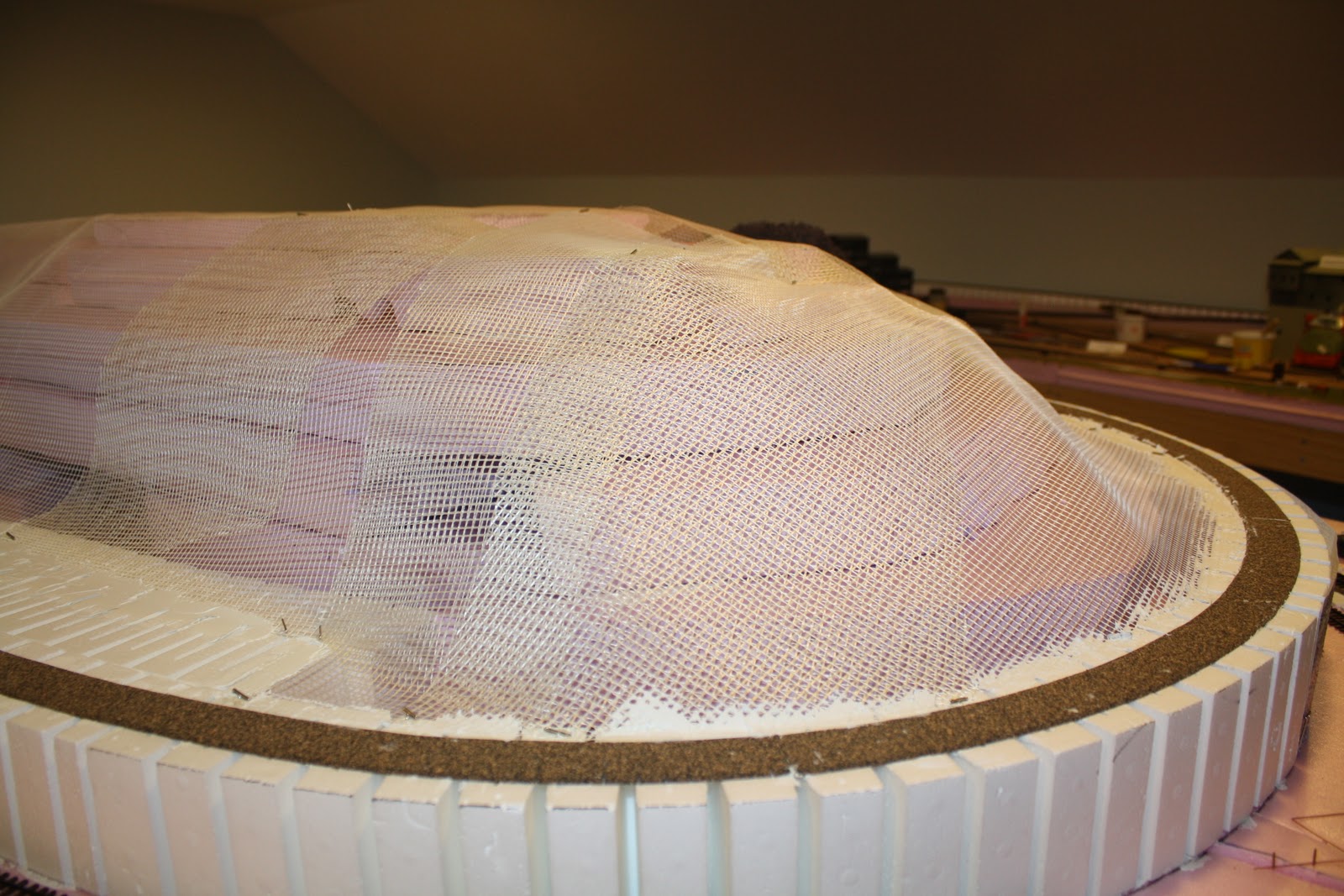
What lies ahead for 2012?  The shop complex at Rockhill Furnace and the company town of Robertsdale are at the top of the list.  Robertsdale was named for one of the principal investors when the EBT was built around 1875.  It was the epitome of  a company town.  The center of the village was called company square and consisted of a large stone company store, a one story station, and two additional stone block buildings: the EBT offices and the Robertsdale post office.  I have nearly completed the scratch built store.  Only the roof remains to be finished.  Next is the station, which will be built from a kit.  The other structures will be scratch built.  Around the center of town will be a number of nondescript company houses.  At the south end of town the tracks will pass the tipple for Mine Number One.  Here are some pictures of where the project stands so far.  You can see that a lot of work remains:


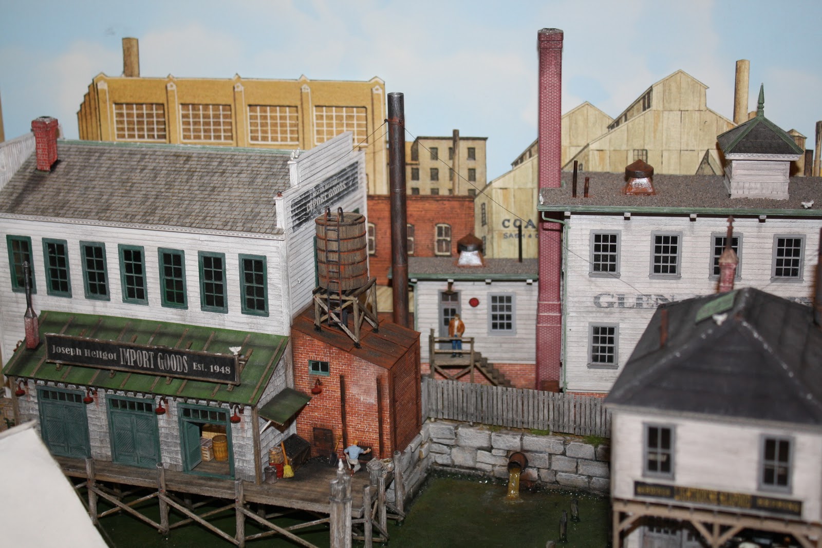
On the other side of the mountain lies Rockhill Furnace, Orbisonia Station, and the main shop complex for the East Broad Top.  Many of the structures are already built for this part of the railroad, most of them from out-of-production White Ground kits.   Still waiting to be built are the locomotive and machine shops, the coal bunker and sand storage shed.  A compressed version of the EBT roundhouse will eventually be scratch built.  Here are a couple of shots of what is already in place.


The challenge here will be to lay out the yard trackage as close to the prototype as space will allow.  What makes this project especially interesting is that most of the Rockhill yard used stub switches and harp switchstands.  At the southern end, as shown in the photo below, the yard throat includes a three-way stub switch.   The problem with stub switches is that, because of the stiffness of the rails, Caboose Hobbies ground throws don't work very well with them.  And, as mentioned in a previous post, it is difficult to mount switch machines on foam.  Added to that, the three way stub calls for some method of stopping the switch in the middle position, not possible with a conventional Tortoise or Switchmaster machine.   I'll certainly keep you posted as work progresses!


A third area of the layout that will require more work in the coming year is Blacklog.   While the town itself is complete, and the yards are largely ballasted (though not yet fully scenicked), the Blacklog Refractories brickyard at one end of town remains to be built.   Here is a rough idea of what the installation will look like when finished.


Finally, I hope to do some work on motive power and rolling stock over the coming year.  Right now I only have one operating steam engine: EBT mikado #14, which has a Tsunami sound decoder, but the lights are not yet wired.  Two additonal mikes -- EBT #16 and #18 -- still need to be painted and weathered, wipers installed on all the wheels, and sound decoders and lights installed.  The EBT's unique gas electric car, the M-1, has a Digitrax decoder without sound.  I need to add wipers, replace the existing decoder with a Tsunami, and install an operating headlight.  And as if all that were not enough to keep an old codger busy, I recently acquired a unique brass model of the EBT's M-3 track car that needs to be painted.   Sounds like a busy year!

Saturday, December 17, 2011

Working With Foam Insulation

Extruded foam is an extremely versatile medium to use in constructing model railroad scenery.  For example, one end of my layout passes by a quarry where ganister rock is mined and moved to a brickyard below by conveyor belt.  The quarry is modeled after a similar operation on Jack's Mountain, above Mount Union, Pennsylvania, where the East Broad Top met the Pennsylvania Railroad.  I built the mountain by cutting smaller and smaller sections of 2 inch foam, to create the impression of a mountainside that has been repeatedly quarried for many years. 


The foam sections were cemented to one another with latex caulk, and covered with plaster cloth. A layer of Hydrocal was then slathered over the cloth.   The face of the quarry was cut from a paper rock formation I found in my scrap box.  With some finely powdered soil and ground foam, the illusion is complete. The rubble cascading down the side of the mountain is kitty litter! 


Extruded foam was also used to form a mountain that functions as a divider running between two towns that in real life were separated by 20 miles, but on my layout are situated back to back.  Blocks of foam were roughly cut into the form of the mountain, then shaped with a type of fiberglas screen used in boat repairs.   The screen was then covered with plaster cloth and Hydrocal, as before.  Here is a view of the mountain before applying the hardshell.  You can clearly see the foam blocks under the screen.


With a little latex paint, some Noch paper rock wall, and a little lichen, the mountain divider begins to look like real scenery!


But while foam insulation is light and easy to work with, it does present some problems for the railroad modeler.  The most common method for constructing a model railroad is to lay Homosote on a base of plywood.  Homosote is a dense paper product that holds spikes and track nails tightly.  The plywood provides a sturdy base for stringing wires and attaching switch machines.  Foam is a softer medium and does not hold screws or nails well.   This can present some real challenges to the modeler. 

The problem of mounting switch machines is a case in point.  Some modelers have mounted the switch machine to a thin piece of plywood, and attached the plywood to the underside of the foam with adhesive.  But most adhesives require that the joint be firmly clamped for several hours to allow it to cure.  Clamping a piece of plywood to the bottom of the foam is not easily done, nor is it practical to screw the wood in place. 

I chose to approach the problem from the top down, rather than from the bottom up.  While most of my turnouts are manually operated with Caboose Hobbies plastic ground throws, there were a few places where the turnout was in an awkward location, or too far from the aisle, and some kind of electromechanical device was necessary.  Rather than mounting the switch machine under the layout, I chose to mount it on top. 

A Tortoise switch machine was attached to a 3 1/2 inch square sheet of 1/8 inch styrene using small nuts and bolts, as illustrated.  A hole the size of the switch machine was cut in the foam with a serrated knife.  After dropping the machine into the hole , I drew the outline of the styrene square on the foam with a magic marker.  Removing the machine, I then carefully carved away about 1/8 inch of foam in the marked off area.  The switch machine assembly was then dropped in the hole again, and after trimming any bumps, the styrene was cemented to the foam with latex adhesive and weighted until the caulk dried.  


The beauty of this method is that should the switch machine ever need to be serviced, it can be unbolted from the styrene and dropped out the bottom of the hole.  Here is a view of the Tortoise switch machine from under the layout.


Another challenge in using extruded foam is how to affix the track to a  medium that does not hold nails well.  It is possible to get around this problem by cementing flextrack directly to the foam (or cork roadbed) with adhesive caulk. The trade-off is a loss of flexibility in moving or adjusting the track. Of course, one could always use brute force, but my best efforts failed to produce the desired result!


Instead, I worked around the problem by cementing 1/8 inch cork roadbed to the foam with latex caulk, then securing code 70 flextrack with track nails and/or spikes pushed into the cork.  In the yard areas I used sheets of cork in the same way.  The cork does not hold the spikes as well as Homosote, but ballasting the track with a dilute mixture of white glue and water tightly bonds the track to the cork.  Here is a photo of the Blacklog Valley mainline affixed to the layout with light gray ballast.


This concludes the series on how I built the benchwork for my model railroad using an open grid wood frame covered with extruded insulation foam.  I hope you found it informative and useful as you consider your own layout.  

Wednesday, December 14, 2011

From Concept to Carpentry

The first step in building the Blacklog Valley was to draw the track plan to scale, in order to make sure it would fit in the available space.  An outline was then drawn around the plan, representing the edges of the benchwork.  While some modelers like to curve the benchwork to conform to the shape of the track plan, I chose to make mine rectilinear, for ease of construction.  However, when drawing the benchwork, be sure to leave space between the tracks and the edge.  None of my trackwork is closer than an inch to the edge of the layout.  Otherwise the trains would be teetering on the lip of a chasm of Grand Canyon proportions!  


Even with a one inch margin, some tracks are perilously close to the edge of the benchwork.  My plans call eventually for installing a plexiglass safety shield in these areas.


Once I had a drawing of the benchwork, the next step was to create a full scale version of it on the train room floor.  I used blue painter’s tape to mark the edges of the layout.  Dimensions were carefully measured, so that the outline would be as accurate as possible.  An error of even an inch or two could make it difficult to lay down the rails according to the track plan.  This could lead to tighter than projected curves, or yard tracks too close together.   Here you can see a section of the benchwork grid with the blue tape marking the edge of the window aisle on the right.


The modules were built using the tape as a guide. In a few cases, where there was sufficient room to expand the track plan, I opted to extend the benchwork beyond the tape boundaries. The 1 x 4 boards were screwed together using #6 x 1 ½ inch flat head screws. Modular sections would be bolted together with carriage bolts.


With a visual representation of the benchwork marked on the floor with tape, it was time to begin cutting lumber and constructing the grid of 1 x 4 boards that would eventually support the foam base, roadbed and track.  I chose to construct the benchwork in modules no more than 8 feet in length, to allow for disassembly if that should ever become necessary. 


Once the grids were assembled on the floor, the next step was to lift them onto the 2 x 2 legs.  Two sides of the benchwork rest against solid walls, so the corner modules were screwed to the walls for maximum support.  Sections of benchwork were clamped to 2 x 2 legs cut to a height of 46 inches.  The corner sections were fitted to the corner of the room, the legs carefully adjusted to ensure the module was level, and a line was drawn on the wall, using a carpenter’s level to mark the top edge of the grid.  The joists were located, and 1 x 4 wooden spacers were screwed to the joists.  The benchwork was then adjusted to line up with the spacers, leveled one more time, and the entire module was attached to the spacers with #8 x 2 ½ inch flat head screws. 


The rest of the layout was then assembled by building out from the corner.   The 2 x 2 legs attached to corners of the benchwork not supported by the wall were fitted with adjustable feet, to allow for leveling once the entire frame was completed. 


Once all sections of the benchwork were attached and leveled, I could see the outline of the layout filling the train room.  Up to this point, it was still possible to make adjustments, or even add extensions to the plan, if necessary. 


Once I was happy with the fit of the track plan, I began to cement slabs of extruded foam cut to the shape of the benchwork.  Before this could be done, however, it was necessary to strengthen the wooden grid that supports the entire layout.  The entire structure was supported on one side by the wall, and on the other by the 2 x 2 legs screwed to the corners of the grid.  A little tug quickly demonstrated that the benchwork was anything but solid and secure.  Without bracing, the slightest touch caused the entire structure to move. 


Cross-bracing was easy to construct.  I cut lengths of 1 x 4 boards to connect the tops and bottoms of adjacent supports, stopping frequently to see if there was any wiggle or sway when I pushed against the benchwork.  The entire structure had to be solid enough to eliminate any movement.  If not, the slightest bump would cause minor earthquakes and derail nearby trains! 


Once the benchwork was solid and secure, it was time to attach the extruded foam to the grid.  Foam can be cut with a sharp serrated knife, or with a hot wire.  Cutting with a knife will result in small pieces of foam on your hands, your clothes, and the floor.  But insulating foam is not nearly as messy to work with as Styrofoam.  Foam insulation comes in 4 x 8 and 2 x 8 foot slabs.  I found it easier to work with the 2 x 8 size, cutting and shaping the foam to fit the shape of the benchwork.  I secured the foam to the wooden grid using Liquid Nails specifically designed for insulation.  Where it was necessary  to layer the foam for more height, latex caulk is an excellent adhesive. 


Although this layout is the fifth incarnation of the Blacklog Valley Railroad, it incorporated several new features: It marked the first time I had designed a model railroad on paper before beginning construction; it was the first time I had fully integrated my own Blacklog Valley with an HOn3 version of the East Broad Top Railroad; and it was the first time I chose to use extruded insulation foam as the base.  Extruded foam is an extremely versatile medium for constructing a model railroad, but it does present some unique challenges.  In the next installment, I will explore some of the pros and cons of this material.

Tuesday, December 6, 2011

Building the Benchwork

There are several kinds of benchwork typically used to support a model railroad.  The simplest is the tabletop design, similar to my first layout.  It is, as the name suggests, simply a flat surface or table on which roadbed and track are laid.  The tabletop approach is often used in modular layouts, and can be seen at train shows and model railroad conventions. 


Another popular approach to building model railroad benchwork is the L-girder system.  This design uses wooden strips that are screwed together laterally to form a long L-shaped girder.  These L-girders are supported by a wooden frame.  The roadbed rests on the L-girders, which can then be moved, raised or lowered in accordance with the track plan.  The roadbed might be a simple cookie-cutter strip of plywood or plywood bonded to homosote; or it might be a series of “splines” made of thin wood strips, separated by spacers, which then support a roadbed of Homosote.  The splines can be treated with steam or hot water to create elegant sweeping curves.  The advantages of the L-girder design are its strength and flexibility.  Although the second incarnation of the Blacklog Valley was not technically L-girder construction, it did incorporate risers and splines, as shown below.


A third common method of constructing the benchwork is the so-called open grid design.  The grid is built of 1 x 3 or 1 x 4 boards, cut and joined to form a grid of supports.  Plywood and Homosote sheets can then be laid on top of the grid.  This was the type of benchwork I chose; but instead of using the grid to support plywood and Homosote, as is usually done, I decided to try a new approach. 

I had for some time been intrigued by the possibility of using panels of extruded foam insulation to support a model railroad.  These sheets come in one and two inch thicknesses, and in various sizes, most commonly 4 x 8 and 2 x 8 feet.  There are two primary manufacturers – Dow Chemical and Owens Corning – and the two brands of foam insulation come in either pink or blue. 


Foam insulation can be easily cut with a serrated or hot knife; it is light in weight but strong; and it can be bonded in layers for building scenery.  It does present some challenges for the model railroader, which I will cover in future postings.  But its advantages were such that I decided to build the latest incarnation of the Blacklog Valley Railroad on an extruded foam base. 


The foam was bonded to the wooden grid with Liquid Nails.  Latex adhesive was used to affix the roadbed to the top of the foam.   In order to increase the elevation, it was a simple matter to bond two or more pieces of foam with latex adhesive.  One of the advantages of using 2- inch foam is that four sections of Woodland Scenics styrofoam incline raise the track elevation exactly 2 inches.


Having designed a satisfactory track plan and set the parameters for my model railroad, it was time to begin construction of the benchwork.   The standard gauge Blacklog Valley Railroad would loop through Blacklog, curve and descend under the highest elevation of the narrow gauge track, make a second loop and climb back into Blacklog in a “folded dogbone”.   The narrow gauge EBT would meet the BVRR at Blacklog, where there would be a dual gauge interchange and wye.  The narrow gauge tracks would climb a 2% grade up to Rockhill Furnace and the EBT shop complex, then continue on through a tunnel and scenic divider, up to Robertsdale and the coal mines on Broad Top Mountain.   All this would be supported by an open grid of 1 x 4 boards and covered with slabs of 2-inch extruded foam insulation.  Track would be laid on cork roadbed – or in the yards on sheets of 1/8 inch cork – cemented to the foam with latex caulk. 


Having made the decision to use an open grid with foam insulation, building the layout moved from theory to carpentry!  At this point the railroad consisted of a pile of boards, boxes of screws and slabs of foam.  In my next post, I will explain how I went about constructing the benchwork, as well as some of the unique problems encountered in using extruded foam as a base for the layout.   

Tuesday, November 29, 2011

Building a Model Railroad: Preliminary Design Issues

In my last post, I developed the rationale for my miniature railroad empire.  With a rationale and purpose for the railroad decided on, I could then move to the design of a track plan that would link together the three main “scenes”of the layout: The small mining village of Robertsdale; the EBT station and shop complex at Orbisonia; and the busy industrial interchange between the Blacklog Valley and the EBT at Blacklog. 
A scale model of anything but the simplest of railroads requires more space than most modelers have available.  Hence, the first step in creating a viable track plan is deciding what to leave out!  Since I model in HO scale (1:87), it quickly became clear that attempting to reproduce the 30-mile long EBT would be impossible.  A one mile long siding in HO would require more than 60 feet!  There simply isn’t enough space.  My train room is a finished bump-out in the attic that measures roughly 19 x 19 feet, with a 10 x 11 foot extension at one end that I use for my workbench, files and storage.  This is a substantial amount of space, but compromises were still necessary.

Thus the first decision in designing a track plan is to determine the maximum available space for the railroad.  In my case, there were windows on two walls of the train room, which complicated the placement of the benchwork.  I decided to leave an aisle along the window walls, placing the benchwork flush against the other two side walls.  This left me with a space of approximately 13 x 16 feet for the layout. 


Knowing the available space is only the first step in layout design.  How to fill that space with an operating model railroad involves a number of critical decisions.  At the very least, these decisions include:
·         The minimum radius of curvature
·         The minimum aisle width
·         The height of the benchwork above the floor
·         The maximum allowable grade
·         The type of benchwork construction.
  
All these questions will affect the design of the track plan, the benchwork, and ultimately, whether you have a model railroad that is interesting and fun to operate, or one that will be a constant source of aggravation and frustration.

Minimum Radius of Curvature
How sharp you make your curves depends on a number of factors, including the wheelbase of the locomotive and the length of the rolling stock.  Many articles have been written on the technical details of building curves on a model railroad; but for simplicity, I opted for a minimum radius of 24 inches for my HO scale Blacklog Valley, and 22 inches for the Hon3 East Broad Top.  In some places the radius is as much as 26 inches; in a few places (such as the wyes at Blacklog and Robertsdale) the curves are somewhat tighter. 


Minimum Aisle Width 
One of the most common errors in building a model railroad is making the aisles too narrow.  In an effort to increase the space for track and scenery, it is tempting to skimp on the width of the aisles.  I have learned through experience that while you may be able to get by with an aisle of 24 to 30 inches, a good three feet is the minimum when there is more than one person operating the trains.  Squeezing by visitors or guest operators is really difficult with anything less.  In my case, the side window aisles are 40 inches wide and the center aisle is three feet. 


Height of the Benchwork 
How high your model railroad is above the floor is a matter of individual taste.  The Lionel train layout my father built for me as a boy, rested on short sections of 2 x 4 placed on edge, making the layout was less than 4 inches off the floor.   This must have made wiring a nightmare!  My own preference is to have the railroad slightly below eye level.  Since I stand about 67 inches tall, I chose to set the height of the benchwork at Blacklog at 46 inches.  This permits me to view trains up close and personal, while allowing for easy access to mechanical and electrical work under the benchwork. 


Maximum Allowable Grade 
The ruling grade is the maximum degree of incline.  Prototype railroads generally operate with grades of less than 2 percent.  A 2 percent grade equals an increase of 2 feet in every 100 feet, which is fairly steep when you are pulling tons of freight uphill.  Some narrow gauge railroads had steeper grades, but rarely more than 3 or 4 percent.  Steep grades meant using helper engines, or sometimes breaking the train into smaller units.  Either solution added to the cost of moving freight.  Railroads were extremely creative in finding ways to avoid steep grades. 

On my layout, I arbitrarily set the maximum grade at 2 percent.  Coincidently, Woodland Scenics sells styrofoam inclines for two, three and four percent grades.  My Hon3 East Broad Top has a steady 2 percent climb from Blacklog to Rockhill, and again from Rockhill to Robertsdale. 


The HO gauge Blacklog Valley Railroad has a 2% descending grade out of Blacklog, such that the return loop passes 5 ½ inches below the narrow gauge EBT at Robertsdale.   In the photo below you can see the standard gauge tracks of the Blacklog Valley emerging from beneath Robertsdale on the HOn3 East Broad Top. 


In my next posting, I will explain how I built the benchwork that supports the layout, and why I decided on extruded foam insulation as the base for the railroad.

Saturday, November 19, 2011

Designing the Blacklog Valley

Like many model railroaders, my interest in the hobby began as a boy, when I received my first Lionel train set for Christmas.  My father had worked secretly in the basement for weeks, building a layout consisting of two 4 x 8 sheets of plywood laid end to end.  To my young eyes, it was perfect, with its painted grass and streets, Plasticville houses, and a figure eight track plan that wound across the miniature landscape. 

I can still remember that wonderful model railroad of my childhood.  So of course, when I built my first layout some 25 years later, I used the same technique: sheets of ½ inch plywood resting between pairs of sawbucks.  To my dismay, I soon discovered that unsupported plywood tends to sag, especially in a damp basement!  Moreover, my first efforts at designing a track plan were less than satisfactory.  I spent more time picking out a name for the railroad than figuring out what it was supposed to do.  Watching a train go round and round in a circle is fun for a while, but eventually it gets boring. 

My current model railroad is the fourth reincarnation of my initial effort.  After some 35 years in the hobby, I have learned a lot about building solid, stable benchwork that provides a suitable support for the track, switches, yards, sidings, and spurs that make up a scenic and interesting model railroad.  I have also discovered the importance of developing a rationale for your model railroad before you begin to build.  In my early efforts to construct a layout, I built the benchwork first, then tried to design a track plan that would fit the available space.  This approach inevitably led to tight curves, inaccessible track, and a “bowl of spaghetti” railroad to nowhere!


Real railroads don’t travel in circles; they are built to carry coal, oil, livestock, merchandise, commodities or passengers from point “A” to point “B”.  Even if your model railroad follows a loop or figure eight track plan, there should be some basic rationale to justify its operation.  That means that before you nail one piece of lumber to another, you need to sit down and decide on a track plan for your model railroad empire.  Only then you can design the benchwork to support your layout. 

In my case, a single thread has connected all five of the layouts I have constructed over the years.  My very first model railroad, built of plywood on sawbucks, was named for a nearby topographical feature in the mountains of central Pennsylvania where I lived.  Blacklog Valley runs in a southwesterly direction from Port Royal, on the former Pennsylvania Railroad, to Hancock, Maryland, and the Western Maryland Railroad.  My first model railroad was named the Blacklog Valley, a bridge line connecting the two class I common carriers.  Every layout I have built since then has included the freelanced Blacklog Valley. 

But while living in central Pennsylvania, I discovered and fell in love with the narrow gauge East Broad Top Railroad, which ran from Robertsdale in southern Huntingdon County, to Mount Union, where it connected with the PRR.  The EBT hauled coal north from the Broad Top coal fields some 30 miles to Mount Union, where the coal was sorted, cleaned, and transferred to standard gauge hoppers.  The EBT also provided ganister rock to several area brickyards, as well as a small amount of freight and passenger service.


I wanted my railroad to include both the free-lanced Blacklog Valley and at least portions of the EBT.  This turned out to be a marriage made in heaven, since the EBT once had a spur that actually served the village of Blacklog, situated in the scenic Blacklog Valley several miles east of the main office and shop complex at Rockhill, Pennsylvania.  Here was the rationale for the layout!  The narrow gauge EBT would haul coal, stone and passengers from Robertsdale through Rockhill to Blacklog, where it would be transferred to the standard gauge Blacklog Valley Railroad. 
With a rationale and purpose for the railroad decided on, I could then move to the design of a track plan that would link together the three main “scenes”of the layout: The small mining village of Robertsdale; the EBT station and shop complex at Orbisonia; and the busy industrial interchange between the Blacklog Valley and the EBT at Blacklog.   In my next post, I will look at some of the issues involved in designing and building a model railroad.

Wednesday, November 2, 2011

Finding Your Niche in the Hobby

Model Railroading is a hobby with something for everyone.   Building a model railroad can involve carpentry, wiring, track planning, scenery, architecture and electronics.  It can lead the modeler to immerse oneself in history, geology, mechanics, and civil engineering.  Some folks like to replicate entire railroads with computerized operations and time clocks.  Others just like to watch the trains go around and around.   There is no right or wrong way to be a model railroader.   The hobby's Rule Number One is paramount: "It's my railroad!"

When you really get into it, model railroading involves a lot of skills, some of which take years to hone.   There are a lot of things I enjoy about the hobby, some of which I am pretty good at, and some I still have a long way to grow.  But over the last 35 years or so, I have found a great deal of enjoyment in building structures -- whether of wood, plaster, plastic or metal.   In fact, I still have most of the models I built when I first got into the hobby.  If memory serves me, my very first foray into structure building was the Timberline Rio Grande Water Tank, which still occupies a place on the layout.


It was probably not the easiest structure to choose for my first craftsman kit, but I learned a lot about building, painting and weathering a basic lineside railroad structure.  If you look carefully, you can see my first attempt to weather the shingle roof with stains radiating out from the center.  Not bad for a first effort. 

My second attempt was even more ambitious -- a bandstand from Campbell.  Even today I can remember what a pain it was to cut and assemble those tiny little lattices.  But I found that building that kit provided so much enjoyment that I was eager to move on to something more challenging:


 It was sometime in the late 1970s that I discovered Fine Scale Miniatures -- marvelous little kits created by George Sellios of Peabody, Massachusetts.  I had never encountered a kit as complicated as his two story station, which came with a whole box full of tiny white metal details: lamps, barrels, architectural ornaments, even a coke machine and a box full of empties!  Nor had I ever purchased such an expensive kit!  (It was almost $30 -- a lot of money to spend on a box containing little pieces of wood, metal and plastic!)   It must have taken me months to build that station, but today it still occupies a place of honor on the layout.  (Recently, I had a chance to chat with George at his fantastic layout, the Franklin and South Manchester.  When I mentioned that I had built the two story station, George got really excited, and told me that it was one of his favorite kits.  It is one of mine as well!)


After the station, I built one more FSM kit, a coal shed and sand house that was, if possible, even more challenging and complex than the station.  It makes me smile to realize that kits that once sold for $25 and $30 back in the 70s now sell for hundreds of dollars!  I loved those kits, but I had reached the point where I wanted to try building something on my own, not from a kit.


By this time I had become an avid reader of Model Railroader and Railroad Model Craftsman magazines.  In the December 1975 issue of RMC there was an article on Retail Coal Dealers with plans for a coal yard with a really neat three silo coal dock.  I decided to strike out on my own for the first time and build a structure with nothing to go on but a set of drawings and some pictures.  The first challenge was how to construct a round coaling tower.  The answer was at hand -- in fact, it was IN my hand -- a cold brewsky that I was sipping while I read the article.  I built the towers from three empty beer cans, wrapped in scribed basswood, with rubber bands for the steel reinforcing rods.  (No, really!  It worked better than you can imagine!)  The end result was a source of immense satisfaction, not least because I did it myself.  I had become a scratch builder!  (The entire structure finally fell apart a few years ago when the Ambroid cement I had used dried out, and the rubber bands finally rotted and broke.  I still have the parts, and one of these days I may try my hand at resurrecting the beer can coaling dock!


The story doesn't end here.  My passion for building craftsman level structures had led me in new and challenging directions.  But that will have to wait for my next posting.

Tuesday, October 18, 2011

Fine Scale Model Railroader Expo 2011

New England is blessed with large numbers of model railroaders (maybe because of our long winters).  What some may not know is that we are also home to a number of small businesses that produce a wide variety of products aimed at those same model railroaders.  In fact, some of these kits are among the best in the country, with manufacturers like George Sellios' Fine Scale Miniatures, Bob Van Gelder's South River Model Works, Brian Bollinger's B.E.S.T. models; not to mention Bar Mills, Atlantic Scale Modelers, Fos Scale Models, Northeastern Scale Lumber Company and a host of others.

On October 14th and 15th I attended the Fine Scale Model Railroader Expo in Peabody, Massachusetts, along with some 300 other modelers and more than 30 manufacturers.  In addition to two rooms full of vendor tables, there were more than two dozen clinics on topics like backdrop painting, tree making, building waterways, lighting, painting, and weathering.  It was a model railroader's dream!


Among the more interesting clinics I attended were: a clinic on selective compression led by Mike Baker; one on prototype structure modeling by Brian and Jill Bollinger of B.E.S.T. models; an outstanding presentation by Jack Ellis of Bar Mills on structure building; and a wonderful conversation with Dave Frary and Bob Hayden on the evolution of their modeling efforts over 35 years of working together. 

One of the more interesting displays at the expo was the "Kit Factory", where you could watch a laser machine cutting out parts for a small passenger shelter, or spin casting metal detail parts, or molds being used to cast a resin tank car.  Afterwards, the parts were handed out as souvenirs for participants.

The expo also included contests for the best structure models, rolling stock and dioramas.  Some of the modeling was truly exceptional.   I gathered up my courage and entered my first contest, using a model I had scratch built of the old farmhouse yard office and attached storage barns at the East Broad Top's Rockhill Furnace shop complex. 

I was rather proud of my little model, having put a lot of hours into it.  But when I saw the caliber of modeling I was up against, not winning came as no surprise.  The surprising thing is that, rather than feeling discouraged, I was energized to improve my modeling skills -- especially in painting and weathering -- for the next time!  One of the exciting things about model railroading is that there is always room for improvement.  Here are a couple of outstanding models that took first prize at the expo.


Of course, everyone looks forward to seeing the latest kits from various vendors.  I was shocked at how much some of these kits cost.  The cost for a Fine Scale Miniatures kit is often $300 or $400, and even less expensive kits by Bar Mills, Fos Scale, or B.E.S.T. run into the hundreds of dollars.  One manufacturer that seems to buck the trend is Jimmy Deignan's Railroad Kits, which had a marvelous display of excellent wood and plaster kits, many of which were less than $100.   I picked up a couple of these bargain basement kits for a reasonable price!

All-in-all, the expo was a great opportunity to meet other modelers, learn about the latest techniques in making and building high end kits, and be re-energized to get back to work on my own layout.  Next year's expo is tentatively slated for Lancaster, Pennsylvania, home of the Pennsylvania Railroad Museum.