
The Current Keeper is somewhat larger than the Econami 100, but there was still plenty of space in the tender for the various components. I decided to mount the sugar cube size speaker under the coal pile, with holes drilled in the coal to allow the sound to escape. Here you can just make out the holes on the coal pile.

The sugar cube speakers are very powerful 8 ohm devices originally designed for smart phones, but they are perfect for those tight places on smaller scale locomotives.

The key to obtaining maximum sound from any speaker is the enclosure. Sound is created by the vibration of a thin metallic membrane, which moves the air around it. The membrane moves the air on both sides, creating sound waves on the front and the back of the speaker. But the sound waves from the front and the back are 180 degrees out of phase. To prevent the sound from one side of the speaker from cancelling out the waves from the other side, the speaker must be fitted to some sort of container that prevents sound waves from escaping both sides at once. Here I have shown a speaker with a wooden enclosure that fits tightly around the back of the speaker. Enclosures can be made from virtually any material, from wood to styrene or even paper! The following picture shows the speaker mounted in the enclosure, ready for installation. I have not yet connected wires to the speaker terminals in this view.

In the next photo, the speaker has been mounted in the tender, facing up, and secured with a piece of green masking tape. The Econami decoder lies on top of the back of the speaker, its wires separated with clothes pins to make wiring easier.

Here is a closer look at the arrangement of wires. Since I did not intend to add special effects lighting other than the headlight, extra function wires were coiled and wrapped with a strip of blue masking tape. The Current Keeper has not yet been installed.

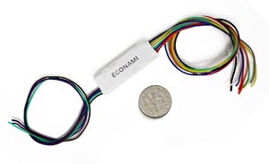
In the following photo, the decoder has been hard wired into place, The Current Keeper is the long purple device next to the white Econami. The wires going to the locomotive include the white lead to the LED headlight. The other headlight wire was connected to the engine shell, eliminating the need for a blue common line to the decoder. The other wires between engine and tender are the orange and gray motor leads and a red wire, which is connected to the frame of the engine for track power from the engineer's side.

The long black wire hanging free from the tender is for track power from the fireman's side of the tender trucks. The Mantua tender was designed to channel track power from the wheels, through the trucks, to the floor of the tender. To ensure a solid contact between the rail and the decoder, I decided to install wipers to the left side tender wheels, and not rely on the axles to carry the power.I made the wipers by soldering a short length of .01" phosphor bronze wire to a small square of printed circuit board, as shown below.

A length of #36 wire was also soldered to the PC board, and channeled through a hole in the bottom of the tender floor. Wires from each of the two trucks were connected to the black wire from the decoder by screwing them together to the floor of the tender. I bored a hole, then tapped for a 2-56 screw to provide power from the tender.

Here is a view of the finished product. The 1.2K resistor is in the headlight circuit. The light is still too bright for my taste, so I plan either to replace the resistor with a higher value or reduce the current to the LED by adjusting the lighting CV on the Econami. If you have a sharp eye, you may also notice a piece of blue tape near the front of the tender. Just to be safe, I installed a solid state fuse to protect the decoder from a power surge to the motor. Once I decided to replace the open frame motor with a Sagami can motor, the danger of such a surge was eliminated, but I left the fuse in anyway.

After successfully testing the decoder on my workbench, I closed up the tender and tried running the engine on the layout. Once I was comfortable with the operation, the next step was to program the decoder CVs for the specific sounds I wanted on EBT #3. A future post will include programming and weathering the engine and installing the standard and narrow gauge couplers on the tender,