The trestle was constructed over a tracing of the rails that would be replaced by the finished structure. Using the kit's template for a 22 inch radius curve, I marked the positions on the curve where the bents would be located. Since the template shows only three bent locations, it was necessary to slide it along the tracing, marking the bent locations for the entire structure. Then I turned the bridge deck upside down, and using the marks I had just made, glued the stringers into position with Pliobond contact cement.

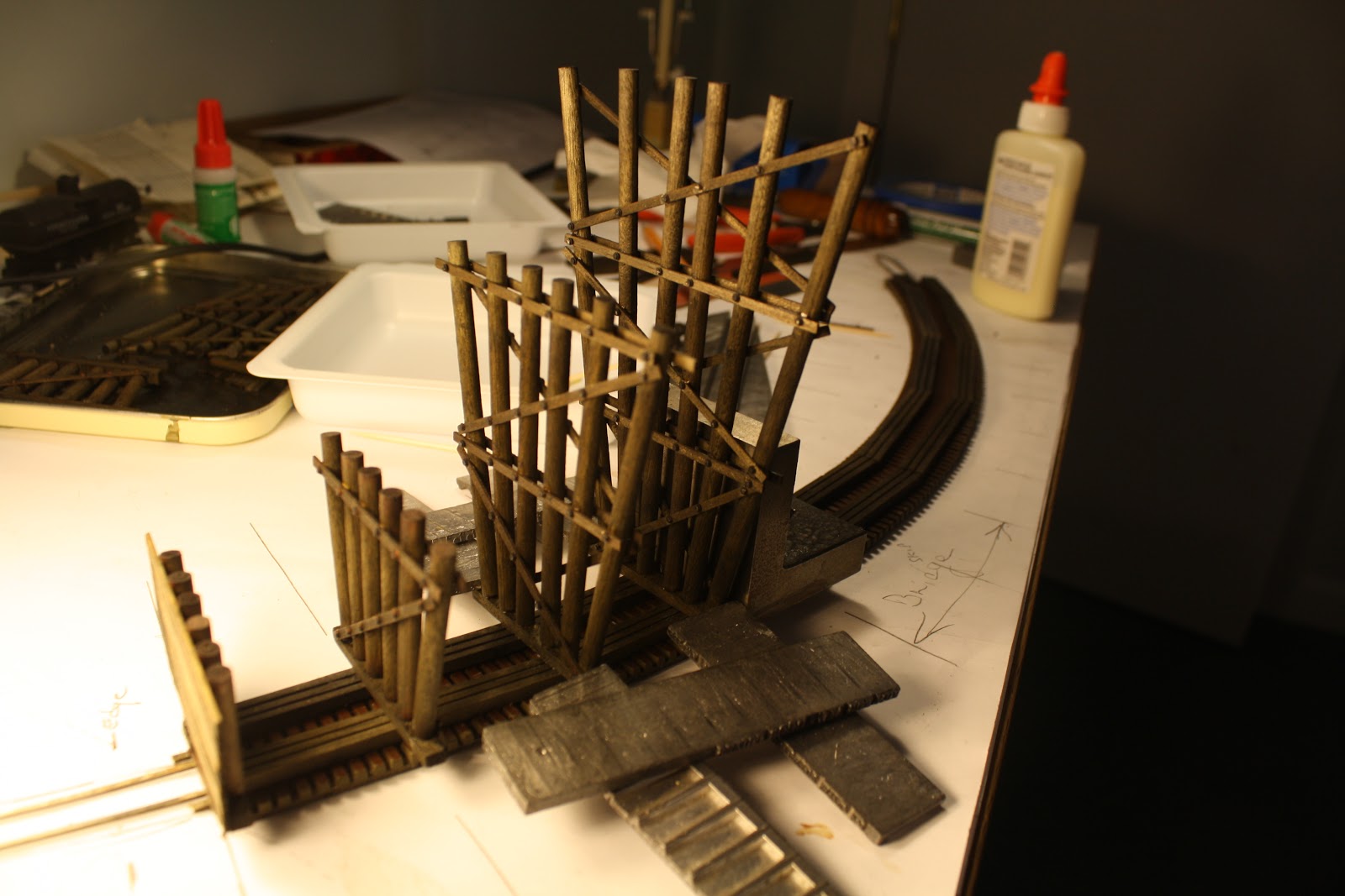
The kit directions called for cutting the stringers to the distance between two bent caps. But prototype trestle construction, particularly on a curved structure, normally has the stringers extend over three bents for added strength. In this next picture, you can see the marks indicating where the bents will be located. Here I am test fitting the first few bents in position on the stringers. The trestle is upside down. The stringers are the grooved wooden pieces to which the bents are glued. One set of stringers runs from the bulkhead to the second bent. The next set of stringers butts agains the first and runs beyond the third bent. You can see where it abuts the next set of stringers. The next bent will fit exactly over the joint between stringers.

Beginning at one end, I glued the bulkhead into position using a machinist's angle plate to insure a 90 degree angle between the stringers and the trestle bent. Lead weights were used to hold the parts in position while the yellow carpenter's glue set.

Here is a view from the other side of the bulkhead. The lead weights were castoffs from an old Linotype press.

Once the bulkhead was fixed, I glued the first trestle bent to the stringers, again using the lines on the tracing to locate and orient the bent.

The process was repeated as each additional bent was glued to the stringers, making sure that the cap was exactly situated over the radius lines drawn from the 22 inch template.
There was no easy way to clamp the bents into position while the glue dried. I used lead weights and a good deal of ingenuity to keep pressure on the bents while also making sure they were at a 90 degree angle to the stringers.

In some cases, applying pressure while the glue dried called for using a variety of objects from around the train room -- for example, here a wooden whistle and a screwdriver serve to keep pressure on one of the longer bents.

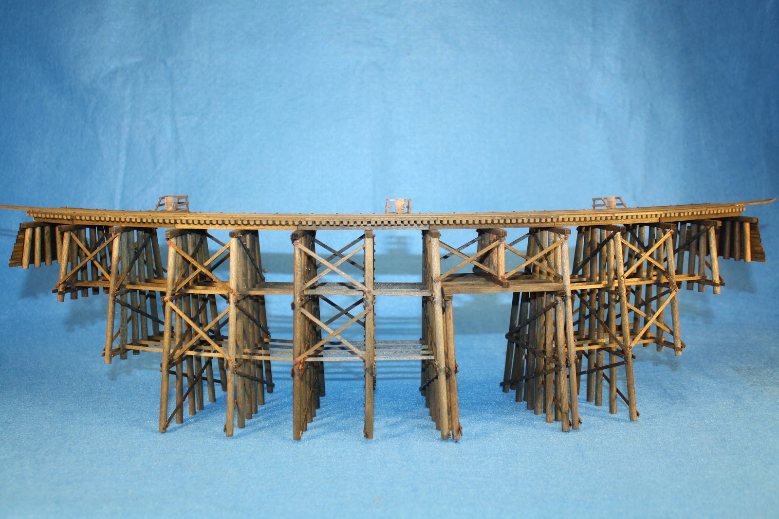
When all the bents were firmly glued in place, I gently turned the entire structure right side up to see how it looked. Even without sway braces and longitudinal braces (or girts) one could see the outline of a 160 foot pile trestle on the workbench!

The noticeable empty space in the center of the picture is where the trestle will pass over a mountain stream on the finished layout. In order to allow the structure to bridge the water, a second set of bents was constructed on either side of the gap, to allow four additional stringers to serve as supports for the center of the bridge. This adds a little interest to the structure. Here you can see the stringers in place.

Just for fun, I tried running a car across the still unfinished trestle. What a thrill, after all the work so far, to see the structure working as intended.

Although the bridge looks impressive, it is still very fragile. All that holds the bents to the stringers, and to the bridge deck and rails, is a thin coating of glue where the stringers rest on the bent caps. I found out the hard way how unstable it was when I accidently put too much sideways pressure on one of the bents, and it came off in my hand! Builders of the real thing understood the problem as well, and used a series of cross braces and longitudinal girts to strengthen the trestle.
The girts are simply long pieces of wood that tie the bents together across the length of the trestle. The problem was how to glue them to the piles and apply pressure long enough for the glue to dry. Again, as when glueing the bents to the deck, some ingenuity is required. I used 1/16 inch square stripwood as levers to press the girt to the pile when the glue was applied. Sometimes the levers required a little help from various sizes of wooden clothespins.


It was surprising how much stronger the trestle became with the addition of the longitudinal braces. The final step was to add cross braces on every other pair of bents, following prototype practice. The finishing touches included adding NBW castings where the cross braces were clearly visible to the observer. I did not bother with the back (or concave) side of the trestle, which will face a rock wall and will not be visible from the aisle. A few touch ups with rust and grimy black weathering powders, and the addition of fire barrels and platforms, and the trestle was ready for installation on my layout.

This concludes my description of how I built the curved trestle. The next step, of course, is the installation of the bridge on my layout, including creation of the scenery that will give it life. That will be covered in Part 4.
No comments:
Post a Comment